


 376 / 948

BRAKES
46
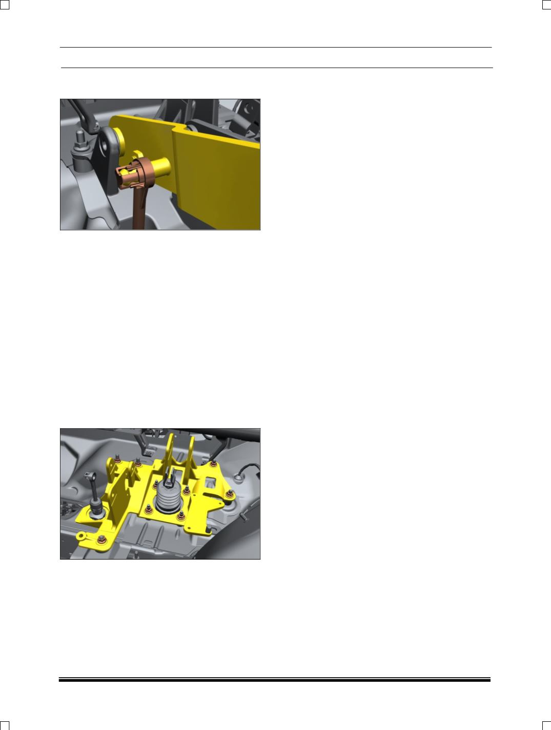
3. Pull out Snaps on clutch master cylinder from
clutch pedal.
FITMENT OF CLUTCH MASTER CYLINDER
ASSEMBLY
For fitment follow the reverse procedure of clutch
master cylinder removal.
CONTROL BRACKET REMOVAL
1. Remove Brake pedal Assembly. (Follow
Brake pedal Removal procedure)
2. Remove Accelerator pedal Assembly. (Follow
Accelerator pedal Removal procedure as
above mentioned in draft)
3. Remove Clutch pedal Assembly. (Follow
Accelerator pedal Removal procedure as
above mentioned in draft)
4. Remove all mountings Hex FL nut M8 on
control mounting bracket & take out bracket.
FITMENT
For fitment follow the reverse procedure of control
bracket removal.
Booster & control mounting nuts tightening torque
2~2.4 kgf-m.
NOTE
At the time of fitment apply thin coat of multi
purpose grease on clevis pin.
Align the axis of brake pedal hole with the
Booster fork hole and after inserting the clevis
pin through Booster fork and brake pedal
check the free rotation of clevis pin.