


 352 / 948

BRAKES
22
REAR DRUM BRAKES
CONSTRUCTION AND WORKING
This brake is designed for use on rear wheels and
is equally efficient in both forward and reverse
direction of movement. A mechanical lever
mechanism is incorporated for normal hand brake
operation. The feature of this brake is that the
brake shoe adjustment takes place automatically
when the service brake is applied.
The leading and trailing shoes are connected at
one end by a two-piston wheel cylinder and an
adjuster assembly. The adjuster assembly
consists of a male and female pushrod with an
adjuster nut operated by a pawl.
Coupled on the trailing shoe is a hand brake lever
which pivots on a pin at the wheel cylinder end of
the shoe.
A spring dowel fitted at the leading shoe provides
a pivot for the pawl lever, which is retained in
position by a spring hooked on to the web. The
hand brake cable passes through a hole in the
back plate, and the slotted cable end fits in the
end of the hand brake lever. When the handbrake
is applied, the cable pulls the lever and this
movement is transferred via the adjuster
assembly to the shoes, which moves outwards
onto the drum. When the foot brake is operated,
both the shoes are pushed on to the drum by the
wheel cylinder pistons. As the shoe linings wear,
the outward movement of the shoes exceeds a
predetermined amount and the pawl pivots on the
spring dowel to rotate the adjuster nut. This action
lengthens the adjuster assembly sufficiently to
reduce the clearance between the brake shoes
and drum to the desired minimum. The
adjustment is repeated, whenever necessary,
according to the rate of lining wear.
BRAKE MAINTENANCE
Note: The rear brake shoes have to be replaced
insets only. If you are replacing brake shoes on
left side brakes then the brake shoes on right side
brakes should also be replaced.
To maintain the efficiency of the brake system,
preventive maintenance is essential and the
following recommendations should be observed at
the intervals stated.
BRAKE ADJUSTMENT
As it is an auto adjust brakes, brake adjustment is
not required.
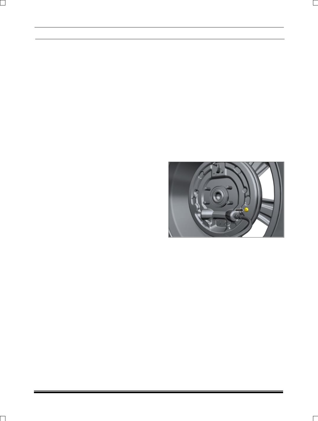
1. Every 10,000 kms check the lining for wear
through the inspection hole provided in the
back plate, removing the
grommet
. The
linings should not be allowed to wear below
1mm lining thickness.
2. Every 20,000 kms clean the back plate and
lubricate the tips of the shoe platforms with
graphite grease and the moving parts of the
adjuster with mineral grease. Keep the grease
away from the shoe lining sand all hydraulic
parts.
3. The wheel cylinder should be overhauled once
in 40,000 kms or 18 months whichever is
earlier.
MAJOR OVERHAUL
It is essential that the shoe linings are inspected
at regular intervals to prevent the drums being
permanently damaged and subsequently making
drum removal extremely difficult.
1. Choke the front wheels, release the hand
brake and jack up the rear wheels. Support
the rear axle with horse stands.
2. Slacken off the hand brake cable.