


 50 / 948

KRYOTEC ENGINE
41
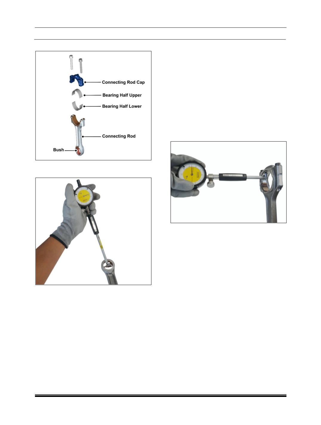
J. CONNECTING ROD
1. Check connecting rod small end visually for
any damage and check the dimensions.
2. Ensure that connecting rod big end and small
end axis are parallel to each other and are
within specified limits.
3. Ensure that the center distance between small
end to big end is maintained within specified
limit.
4. Smear oil on parent bore of connecting rod.
5. Install connecting rod bearing caps without
bearing shells on connecting rod.
6. Tighten connecting rod bearing cap mounting
bolts to specified torque.
7. Ensure that identification numbers for
connecting rod and connecting rod bearing cap
are matched and notches for bearing shells are
on the same side.
8. Check twist and bend of connecting rod by
using new piston pin in connecting rod small
end bush.
9. Measure twist and bend of connecting rod with
feeler gauge with respect to vertical face of the
connecting rod alignment gauge in vertical and
horizontal plane at a distance of 50 mm from
line joining centers of connecting rod small end
and big end bosses.
10. Check connecting rod big end parent bore
dimension.
11. Ensure that the connecting rod big end and
small end axis are parallel to each other within
the specified limits. Center to center distance
between connecting rod small end and big end
is maintained within specified limits.
12. If one or more connecting rods are to be
replaced, ensure that difference in weight of
connecting rod in one engine is within
permissible limits.
13. Install new pair of connecting rod bearing shell
according to size of crank pin journal diameter,
making sure that securing lugs of bearing
shells are properly seated in grooves of
connecting rod and its bearing cap.
NOTE
Lower
and
Upper
bearings
are
not
interchangeable.