


 410 / 948

Anti-lock Braking System(ABS)
18
NOTE:
ABS ECU and is not serviceable.
Refer ABS troubleshooting for faults related to
ABS ECU.
Installation :
1. Follow the reverse order of removal to install
the ECU on the mounting bracket i.e. :
a. Insert the left side damping element.
b. Slightly tilt forward and insert the centre
pin in centre damping element.
c. Insert the right side damping element.
d. Ensure that the ECU is seated properly
and tighten the holding nuts to a torque of
0.8 ± 0.2 Kg-m.
2. Reconnect the brake lines. Be certain that the
brake lines have been connected to the
correct ports to ensure proper ABS operation.
Tighten the coupling nut to specified torque.
(1.4 – 1.8 Kg-m)
3. Connect the ECU connector.
4. Bleed the brake system.
NOTE :
For brake bleeding procedure conventional/ using
diagnostic tool refer Brakes group.
5. Clear all faults using diagnostic tool.
6. Road test the vehicle to ensure proper
operation of the conventional brakes and ABS
system.
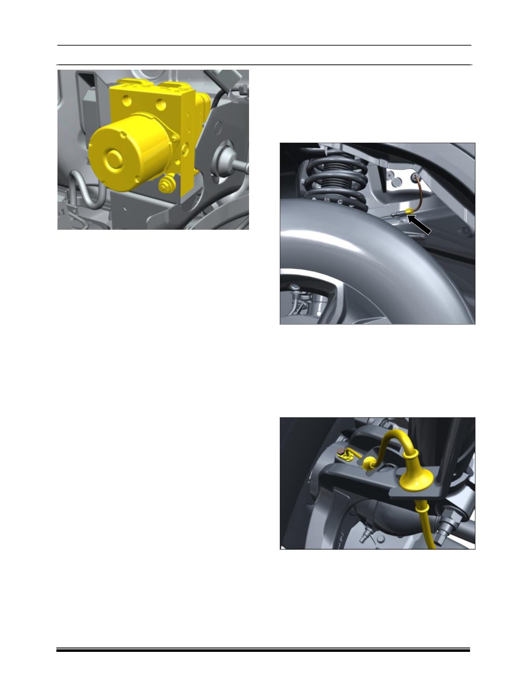
B. FRONT WHEEL SPEED SENSOR :
Removal:
1. Position the vehicle on two post lift.
2. Disconnect electrical connector of wheel
speed sensor located on the bracket at the
rear of the front suspension tower.
CAUTION:
Take proper precautions while disconnecting the
wheel speed sensor from vehicle wiring harness,
otherwise it might damage the pins of the
connecter.
3. Remove sensor mounting screw and remove
the wheel speed sensor from the steering
knuckle.