


 366 / 948

BRAKES
36
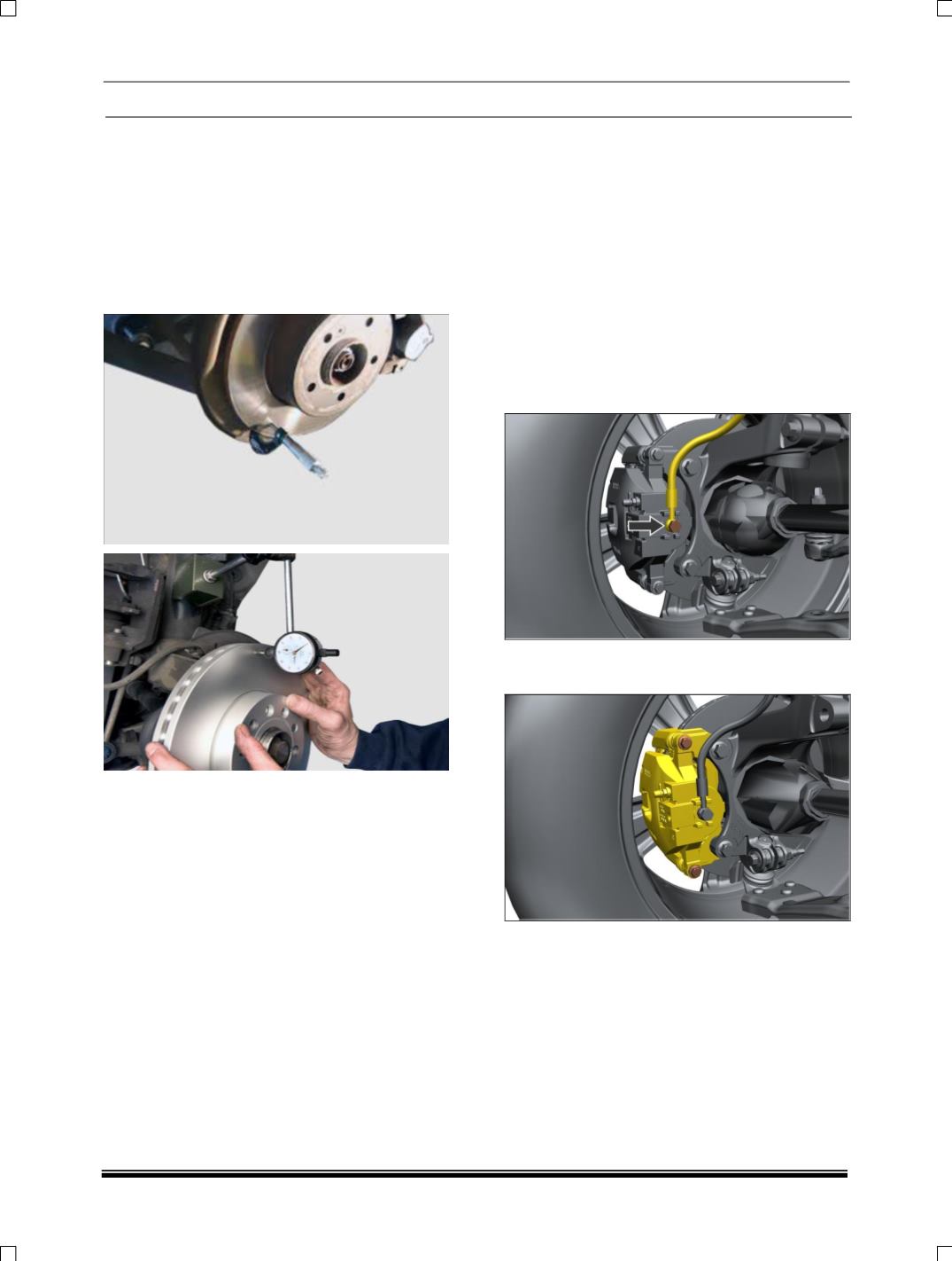
During measurement, confirm the dial gauge
probe should be approx. 10 mm from the outer
edge of the brake rotor, perpendicular to the disc
and under slight preload.
Check front wheel bearing for looseness before
face runout measurement.
The control of the braking surface finish is
necessary to avoid pulls and erratic performance.
It will also help in extending pad life.
17.ONVEHICLE REPAIRS
A. CALIPER ASSEMBLY WITH CARRIER
REMOVAL
1. Apply parking brake & keep the gear shift lever
in neutral position.
2. Jack up the front of the vehicle and remove
wheels.
3. Remove hose from caliper body by taking out
the banjo bolt and collect the brake fluid from
caliper in a clean container. Block the brake
hose using a dust cap to prevent loss of brake
fluid and prevent contamination and keep the
pipe in the vertically up-straight position.
4. Loosen and remove the mounting bolts of
caliper assembly.
5. Remove the caliper assembly along with the
carrier from the brake disc.
NOTE
If only the caliper housing has to be removed.
Remove the caliper pads. (Refer caliper pad
replacement in regular maintenance)