


 950 / 1232

SRS
22
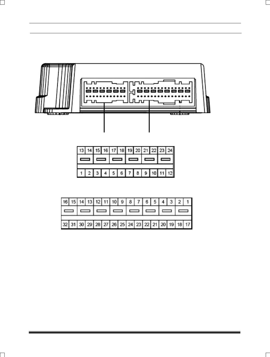
10.7 SRS ECU PIN OUTS:
Connector A Connector B
Connector A (Pins orientation)
Connector B (Pins orientation
NOTE:
The mating connector shall be separated by 2 ways (24pins and 32pins): Main connector partition
is for connections to the instrument panel area such as power, communications, AWL, front
remote sensing unit, frontal firing loops etc. the second connector portion is for vehicle body
connections such side & curtain airbag modules, side impact sensors etc.