


 698 / 1232

SUSPENSION
19
20. Pull out knuckle bearing using puller part No.
2779 5890 3302
INSTALLATION:
1. Follow the above steps in reverse order in
appropriate sequence for its assembly.
NOTE:
High / Low point matching on Hub and Disc
Observe the condition of disc surface. If the disc
surface is smooth ensure that punch mark (Low
Point) on disc and hub (High Point) are aligned
and assembled.
If the disc surface is uneven showing rough
marks, grooves - machine it to the specified limit;
measure the run out on dia 220 w.r.t. hub and
disc resting face.
Punch mark around bolt hole where run out on dia
220 is at low point.
Align low point on disc and high point on hub
while assembly. Assemble with countersunk
screws.
2. Tighten drive shaft nut 23 to 26 mkg torque
and lock by staking.
3. Ensure that oil seal in transaxle is not
damaged while fitting drive shaft.
PRECAUTION:
Use a new hub bearing and new circlip, oil the
bearing housing in knuckle carrier and hub itself.
Old bearing, even if serviceable cannot be
reused.
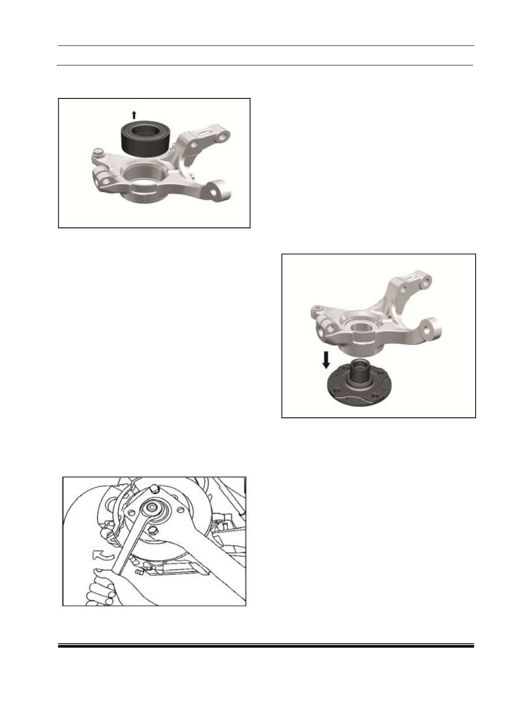
SUB ASSEMBLY - KNUCKLE / HUB:
Clean all the parts thoroughly and replace
damage / worn out parts.
1. With the help of drift part No. 2779 5890 3301
and 2640 5890 3511 fit bearing in the knuckle
2. Fit circlip.
3. Place the knuckle assembly over the hub.
Using drift part No. 2576 5890 4401 press the
knuckle assembly on the hub.