


 198 / 1232

Revotron 1.2T
151
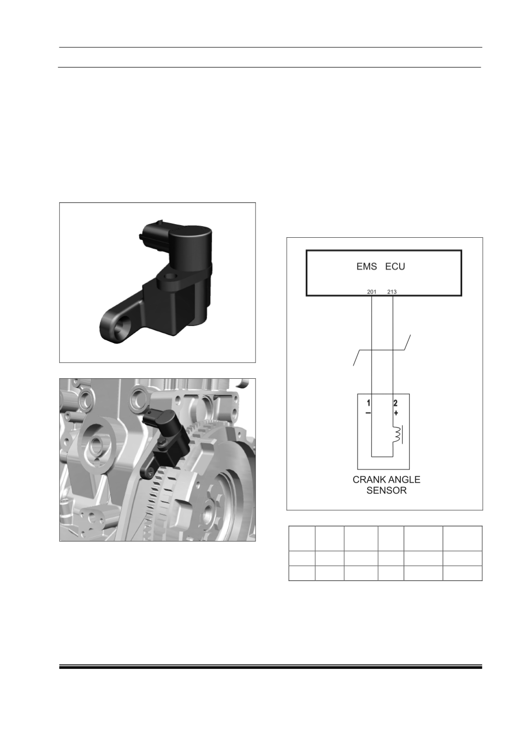
v. Crankshaft Position Sensor :
Component Details :
The circuit decodes the signal given by an
inductive based sensor (Variable Reluctance).
Intended target is a wheel uniformly cut with
60 teeth and 2 teeth removed. The sensor
output signal approximates a sine wave
whose frequency is proportional to engine
speed and amplitude is approximately
proportional to engine speed. Active edge is
generated from zero crossing point positive to
negative transition.
Component Location :
Preliminary Checks :
1. Loose/Damaged Connections between
sensor and EMS ECU.
2. Check for back out of pins at both sensor
connector and ECU connector.
3. Check for damage of pins at both sensor
connector and ECU connector.
4. Check the continuity from sensor
connector pins to the ECU pins.
5. Physical damage to flywheel.
6. Improper Air Gap between sensor and
flywheel.
Circuit Schematic Diagram :
Connector Information :
Con
ID
Wire
ID
Color Size Material
Option
1
369
W
0.75
ISCT
(AD)
2
368
B
0.75
ISCT
(AD)