


 125 / 1232

Revotron 1.2T
78
Description :
The lubrication system layout is as shown
in the schematic above. The G-rotor oil pump
is mounted on the crankcase. Oil is drawn up
from the sump through oil pump strainer and
passes through the pump to Oil Filter.
The filtered oil flows through the internal
drilled holes into the crankshaft oil gallery
from here it is supplied to connecting rod
bearings and also to the main bearings by
means of intersecting passages drilled in the
crankshaft. It is then injected through the
cooling nozzles to the underside of the piston/
piston gallery for cooling. There is a separate
line that goes to lubricate the turbocharger.
There is another path which takes the oil
up from the crankshaft oil gallery to camshaft
oil gallery in cylinder head and lubricates the
camshaft. The camshaft oil gallery also
provides the oil needed by rocker arm. The
relieved oil drains back to oil sump.
The lubrication system consists of the
following components.
1. Turbocharger
2. Oil Pump
3. Strainer
4. Oil Sump
5. Oil Filter Assembly
6. Oil Pressure Switch Sensor
7. Crankshaft
8. Piston Cooling Nozzle
9. Piston-Connecting Rod Assy.
10. Vacuum Pump
11. Camshaft
12. Rocker Shaft
13. Rocker Arm
Components :
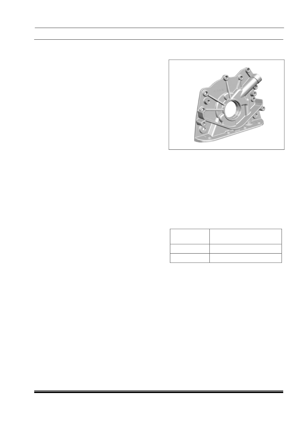
1. Oil Pump :
Oil Pump is directly driven with
crankshaft.
The main function of the oil pump is to
circulate oil through the engine movable
components. It sucks the oil from the oil
sump through a strainer which prevents
entrance of any particles into the pump, and
supplies to the oil gallery.
To keep the oil pump from building up too
much pressure, a relief valve is also fitted to
the oil pump.
OIL PUMP SPECIFICATION :
Pump Speed
(RPM)
Flow Rate in LPM (Min) at
3bar back pressure
800
7
4000
34