


 311 / 1232

ENGINE 1.3 QUADRAJET (75PS)
86
1. Connection lead
2. Protective sleeve
3. Planar sensor element
4. Ceramic support pipe
5. Sensor seat
6. Ceramic seal
7, Protective pipe
ELECTRICAL SPECIFICATIONS:
Q
Max 7.5 V heater power supply from control unit
Q
Heater resistance 3.2 ± 0.8 Ù
PIN OUT
1. Pumping current (lp)
2. Virtual mass
3. Heater (-)
4. Heater (+)
5. Calibration current
6. Nerst voltage
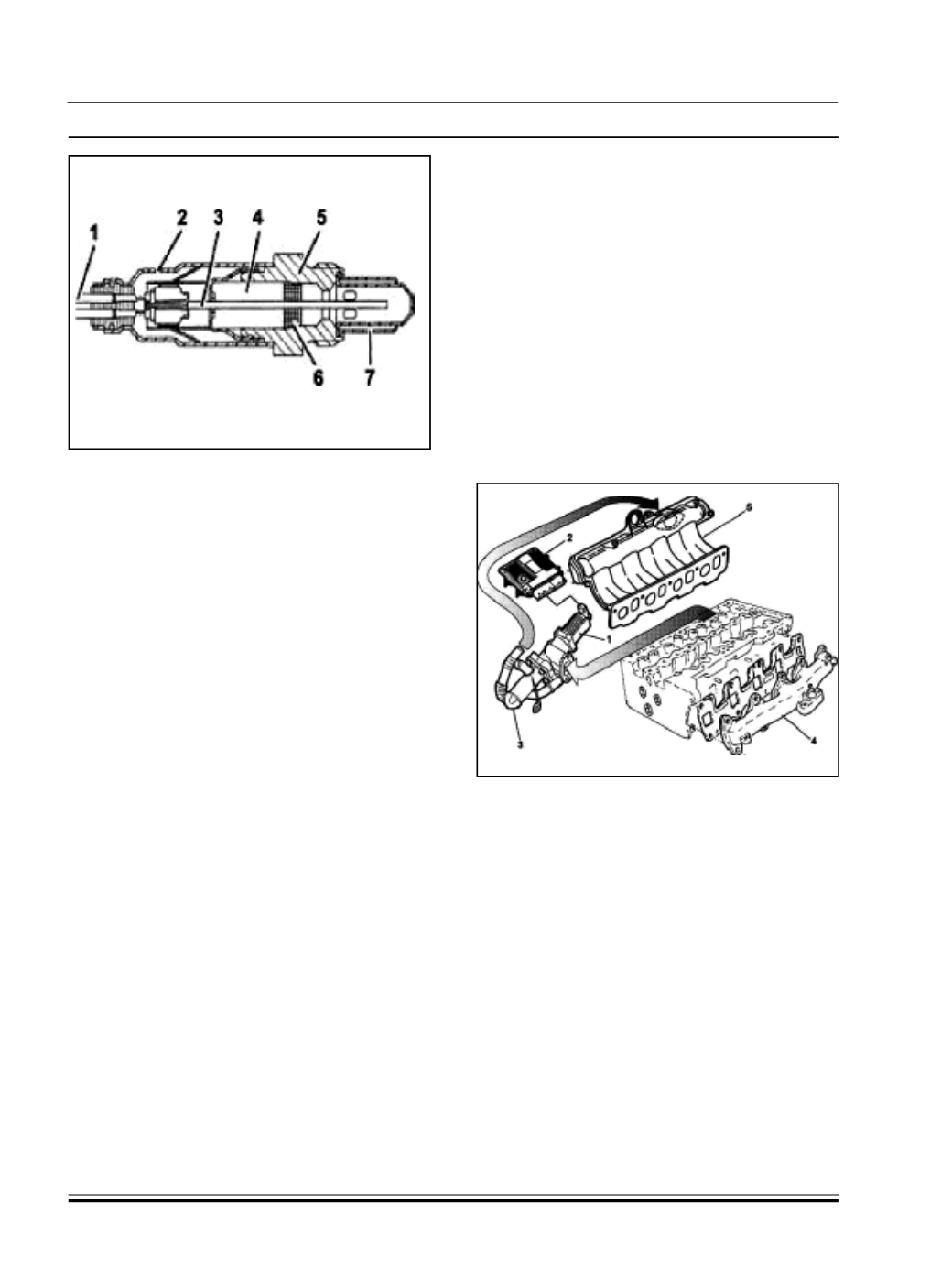
C. EXHAUST GAS RECIRCULATION (EGR).
This system makes it possible to send some (5 - 15%)
of the exhaust gases to the intake in certain operating
conditions.
This lowers the peak temperature in the combustion
chamber restricting the formation of nitrogen oxides
(NOx).
The E.G.R. solenoid valve (1) operated by the injection
control unit (2) carries out the t ask of reintroducing
some of the exhaust gases t aken from the exhaust
manifold (4) back into the engine intake.
A heat exchanger (3) allows the partial cooling of the
exhaust gases further lowering the temperature of
the combustion chamber.
1 - EGR solenoid
2 - Injection control unit
3 - Heat exchanger
4 - Exhaust manifold
5 - Air intake manifold
WORKING
At coolant temperatures of > 20°C with the engine
speed between 800 and 3000 rpm, the injection
control unit operates the E.G.R. solenoid valve with a
square wave signal.
The variation in this signal allows the E.G.R. coil to
move a shutter, thereby regulating the flow of exhaust
gases from the exhaust manifold to the int ake
manifold; there are two results: