


 107 / 1232

Revotron 1.2T
60
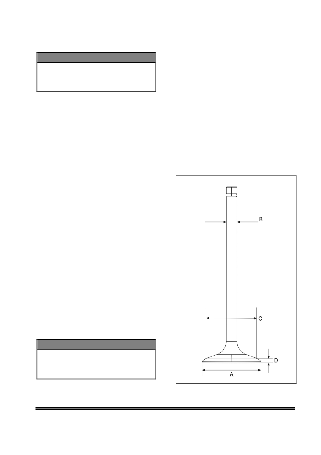
C. Valves :
DANGER
•
Petrol and Petrol fumes are extremely
explosive!! use caution when working with
gasoline, otherwise explosion or fire may
occur, causing severe burns or death.
1. Check for leakage past the valves and valve
seats by placing the intake and exhaust
valves in the cylinder head and pouring
gasoline or isopropyl alcohol in the valve
chamber. Leakage indicates damaged valve
seats and/or valves. Note the location of each
valve so the valve can be matched to the
same location during reassembly.
2. Inspect each valve for damage. Do not
attempt to repair damaged valves. Replace
valves exhibiting the conditions in the
following list.
•
Burnt head or excessive carbon deposits.
•
Scoring or scratches on the valve surface
•
Excessive wear
3. Check for bent valves and excessive runout
between valve seat and stem by placing the
valve in a measuring fixture.
4. Place a dial indicator on the valve head and
valve stem and rotate the valve, observing
movement on both dial indicators.
5. The maximum permissible runout for both
exhaust and intake valve is 0.030 mm.
6. Measure the other valve dimensions listed in
table. If the only defect is a worn valve face or
seat, machine the valve and seat to match.
Otherwise, replace the valve.
7. To machine the valve, clamp the valve in a
grinding machine as close to the valve head
as possible.
8. Adjust the grinding angle to achieve a 45
0
grind on the valve seat.
9. Carefully feed the valve towards the grinding
wheel until the wheel just reaches the head.
10. Grind the valve seat until the complete face of
the seat is clean from machining.
NOTE
•
After machining the valve seat, remove the
valve from the grinding machine and check
valve head thickness. The minimum valve
head thickness of the valve is 0.85 mm.
11. Lap the valves and valve seats to smooth and
even finish using lapping paste and a hand
pump grinder or by inserting the valve into the
cylinder head and rotating to achieve the
proper finish.
12. Coat the valve seat with carbon blue/ prussian
blue dye and insert the appropriate valve into
the cylinder head.
13. Rotate the valve under axial pressure several
times and remove from the cylinder head.
14. Inspect the area of contact created by the
axial rotation of the valve.
•
The contact pattern should be equal and
unbroken around the circumference of the
seat.
•
The distance from the narrow diameter of
the valve seat face to the contact line
should be 0.5 mm.