


 231 / 1133

1.2L REVOTRON ENGINE
193
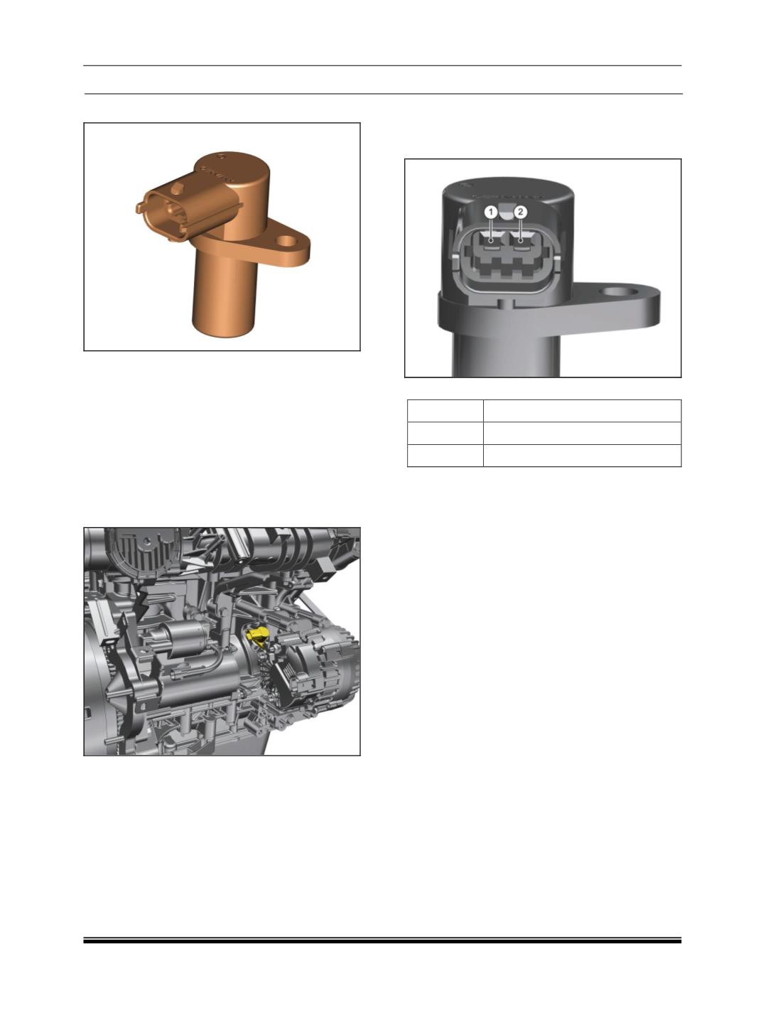
V. CRANKSHAFT POSITION SENSOR
COMPONENT DETAILS:
The circuit decodes the signal given by an
inductive based sensor (Variable Reluctance).
Intended target is a wheel uniformly cut with 60
teeth and 2 teeth removed. The sensor output
signal approximates a sine wave whose
frequency is proportional to engine speed and
amplitude is approximately proportional to engine
speed. Active edge is generated from zero
crossing point positive to negative transition.
COMPONENT LOCATION
PRELIMINARY CHECKS
1. Loose/Damaged Connections between sensor
and EMS ECU.
2. Check for back out of pins at both sensor
connector and ECU connector.
3. Check for damage of pins at both sensor
connector and ECU connector.
4. Check the continuity from sensor connector
pins to the ECU pins.
5. Physical damage to flywheel.
6. Improper Air Gap between sensor and
flywheel.
CONNECTOR DETAIL
PINOUT DETAILS
PIN
DESCRIPTION
1
Ground -
2
Signal
COMPONENT SPECIFICATION
Crank angle sensor provides engine speed and
crank angle input to ECU. 58 teeth are spaced at
an angle of 60 each on the flywheel and two teeth
missing at 114° ATDC (Top Dead Centre) of
cylinder 1 allows the piston position to be
determined. Crank angle sensor is positioned on
these teeth, so that an AC voltage is induced in
sensor coil, when the flywheel tooth projection
passes through the sensor. The AC voltage is
proportional to the speed of rotation. The sensor
is mounted in the engine compartment. It is used
for the detection of the crankshaft position and
speed. The sensor detects the slots and teeth of a
ferromagnetic target wheel and delivers an
electrical signal according to the movements of
the target wheel. Therefore the signal represents
the speed and position of the crankshaft. Proper
function of the sensor can only be covered, if the
specified mating connector is properly assembled.
All wire seals have to be in place. With an
unsealed connector the sensor will not be
waterproof. Crank angle sensor is an inductive
type 2 pin connector, is mounted on cylinder block
over the crank sensor wheel. Sensor gap to be
maintained -: 1.0 ± 0.4 mm Mount the sensor
using a suitable bracket and tighten the bolt to the
specified torque.
OPERATING PRINCIPLE
Due to the rotation of a ferromagnetic target
wheel in front of the DG the magnetic field of a