


 216 / 561

TIAGO/TIGOR AMT Gasoline
DTC Troubleshooting Guide
Version: 4.0
Date: 18-04-2017
Author: Sathi/Anupama
Page: 82 of 427
Copyright ©
TATA MOTORS Ltd.
This document must not be used in any way, such as copying and redistributing to third parties, without the consent of author.
25.
P0820/P0821/P0822/P0823-01: Gear Lever Sensor Circuit– Under min. Threshold
Overview:
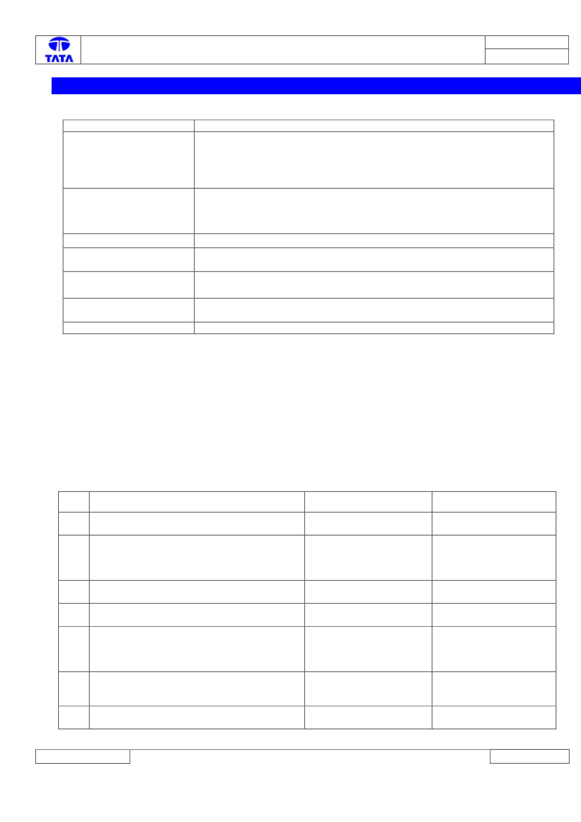
ISO Code
P0820/P0821/P0822/P0823-02
Customer Symptom
Transmission Fault Lamp ON,
Creeping inactive,
Transmission going automatically to neutral from gear when coming to halt after
drive.
Vehicle not cranking
Fault Effects (On Vehicle)
Creeping inactive,
Transmission going automatically to neutral from gear when coming to halt after
drive.
Vehicle not cranking
Lamp Status (If Any)
Transmission Fault Lamp ON
Fault Detection Condition
This fault gets detected after Ignition On if any of the 4 GSL sensor signals is
found below a calibratable threshold.
Normal Operating
Condition
All 4 GSL sensor signals will be in a valid operating range.
Probable Trouble Area
Wiring Harness Connections / Sensor / TCU
Healing Condition
2000 milliseconds after valid sensor signal
Component Details:
The Gear Lever outputs four hall sensor signals which encode the position of the Gear lever.
Preliminary Checks:
1) Loose/ Damaged Connections between Sensors and TCU.
2) Check for damage or back out of pins at Gear lever connector and TCU connector.
3) Check correct fitment of ground cable connections on vehicle chassis.
Trouble Shooting:-
DTC’s P0820,P0821,P0822 and P0823 correspond to fault in signals GSL0,GSL1, GSL2 and GSL3 respectively so the
corresponding signal should be checked with due care.
Step Checks
IF YES
IF NO
1.
Is there any rust/oxidation observed on Sensor
Terminals (GSL connector)
Clean the Rust or repair or
replace
Go to Step 2
2.
Is there wiring harness electrical continuity
between TCU pins to GSL Lever connector
pins.
Go to Step 3
Establish continuity by
rectifying harness
connections as per the
circuit schematic
3.
Are there any pins damaged at GSL lever
connector or TCU Connector
Replace the connector or
wiring harness.
Go to step 4
4
Are there any pins backed out from the GSL
lever or TCU Connector
Rectify/Replace
Connectors
Go to Step 5
5
Are any GSL Sensor Signal Pins Short
circuited to GND/Battery? Check for inter-short
among themselves also. (check pins 17, 15, 13
and 11 at TCU 28 pin connector)
Repair the harness as per
the schematic
Go to Step6
6
Check Ignition and ground connections on
Lever connector (pin 3 and pin 1 respectively
on lever 6pin connector), are they OK?
Go to Step 7
Repair the harness as per
the schematic
7
Fault Still Persists?
Replace GSL lever, if fault
persists Replace TCU
Follow the steps again for
reconfirmation