


 193 / 561

TIAGO/TIGOR AMT Gasoline
DTC Troubleshooting Guide
Version: 4.0
Date: 18-04-2017
Author: Sathi/Anupama
Page: 59 of 427
Copyright ©
TATA MOTORS Ltd.
This document must not be used in any way, such as copying and redistributing to third parties, without the consent of author.
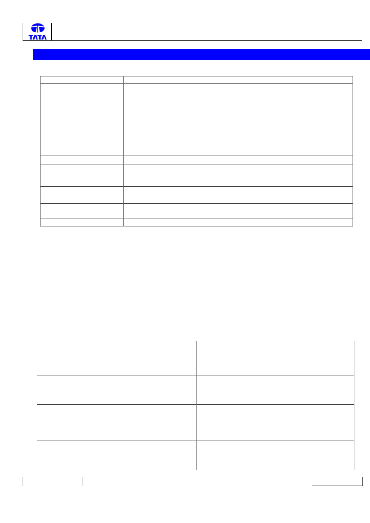
18.
P1852-02: Clutch Position/Hyd Press Sensor – Wrong supply voltage Vbatt Error
Overview:
ISO Code
P1852-02
Customer Symptom
Transmission Fault Lamp ON,
Loss of power while driving.
Engine not cranking
Engine stalling at low vehicle speeds
No gearshift
Fault Effects (On Vehicle)
Transmission going automatically to neutral while driving.
Engine not cranking
Engine stalling at low vehicle speeds
No gearshift
No EOL self-tuning.
Lamp Status (If Any)
Transmission Fault Lamp ON
Fault Detection Condition
This fault gets detected after Ignition On when the Engine is not cranking and
battery Supply voltage is in proper range and the clutch position/Hydraulic
Pressure sensor supply voltage is found to be higher than acceptable threshold.
Normal Operating
Condition
Clutch position/Hydraulic Pressure sensor supply voltage is regulated at 5 V by
TCU
Probable Trouble Area
Harness or connector damage/short, Sensor loose/damage/short, TCU internal
damage
Healing Condition
50 milliseconds after valid sensor signal
Component Details:
Clutch position/Hydraulic Pressure sensor supply voltage is regulated at 5 V by TCU. The clutch position sensor is supplied
through pin 12 (12 pin system connector) and hydraulic pressure sensor through internal TCU connection.
Preliminary Checks:
1) Loose/ Damaged TCU system connector (12 pin).
2) Check for any visible damage to TCU pins, clutch sensor/hydraulic pressure sensor and its pins.
3) Check correct fitment of ground cable connections on vehicle chassis.
Trouble Shooting:-
On first occurrence, clear the DTC and drive the vehicle for 2-3 kms, read the DTC again. On fault confirmed again, follow
below steps.
Step Checks
IF YES
IF NO
1.
Is there any rust/oxidation/pin back out
observed on 12 pin system connector pins 1, 8
&12.
Clean the Rust or repair
or replace
Go to Step 2
2.
Is there wiring harness electrical continuity
between 12 pin system connector pins 1,8
&12.toSensor connector pins 2,1 &3?
Go to Step 3
Establish continuity by
rectifying harness
connections as per the
circuit schematic
3.
Are there any pins damaged at Clutch Sensor
Connector?
Replace the system
wiring harness.
Go to step 4
4
Is Clutch Sensor Supply Pin (pin 12 of 12 pin
system connector) Short circuited to
GND/Battery?
Repair the harness as per
the schematic
Go to Step 5
5
Unmount and remove the TCU from the valve
body. Inspect the condition of the Hydraulic
pressure sensor contacts (refer fig below). Are
the sensor contacts visibly undamaged?
Go to Step 6
Replace the Hydraulic
Pressure sensor/TCU.