


 674 / 1131

BRAKES
29
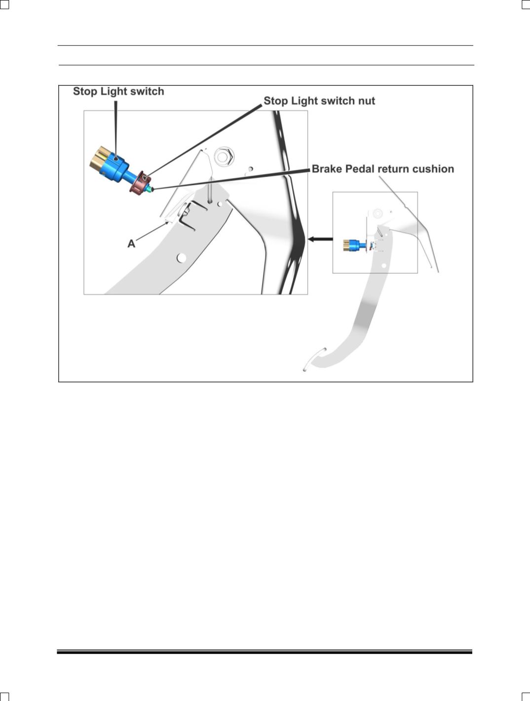
STOP LIGHT SWITCH ADJUSTMENT
NOTE:
Before performing stop light switch
adjustment, ensure that booster is connected
with clevis pin.
Ensure brake pedal is assembled with booster
and confirm bleeding completed. This will
ensure brake pedal initial position,
(This is the condition to ensure prior to
assemble of brake light switch.)
Ensure the dimension “A” between threaded body
end of switch and brake pedal return cushion =
2.0 ± 0.5 mm