


 124 / 1131

1.2L REVOTRON ENGINE
86
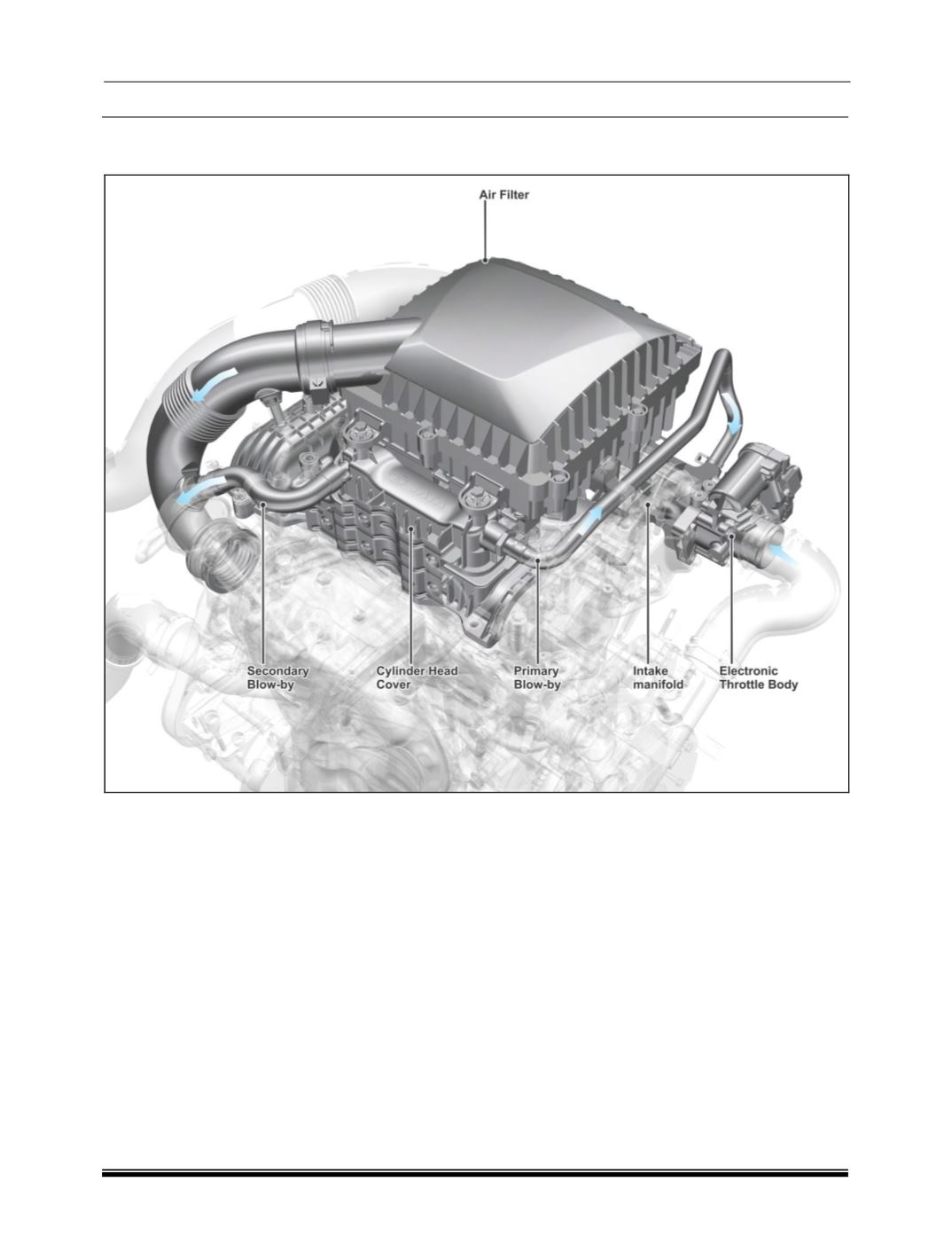
B. BLOW BY SYSTEM
Blow By Schematic Layout
1
Cylinder Head Cover
4
Throttle body
2
Cylinder Head
5
Primary Blow-By Hose
3
Intake Manifold
6
Secondary Blow-By Hose
DESCRIPTION
In order to reduce the blow by gas emission, the
blow by gas is directed to the intake manifold.
Blow by gases are drawn from cylinder head
cover and crankcase.