


 91 / 1906

ENGINE
55
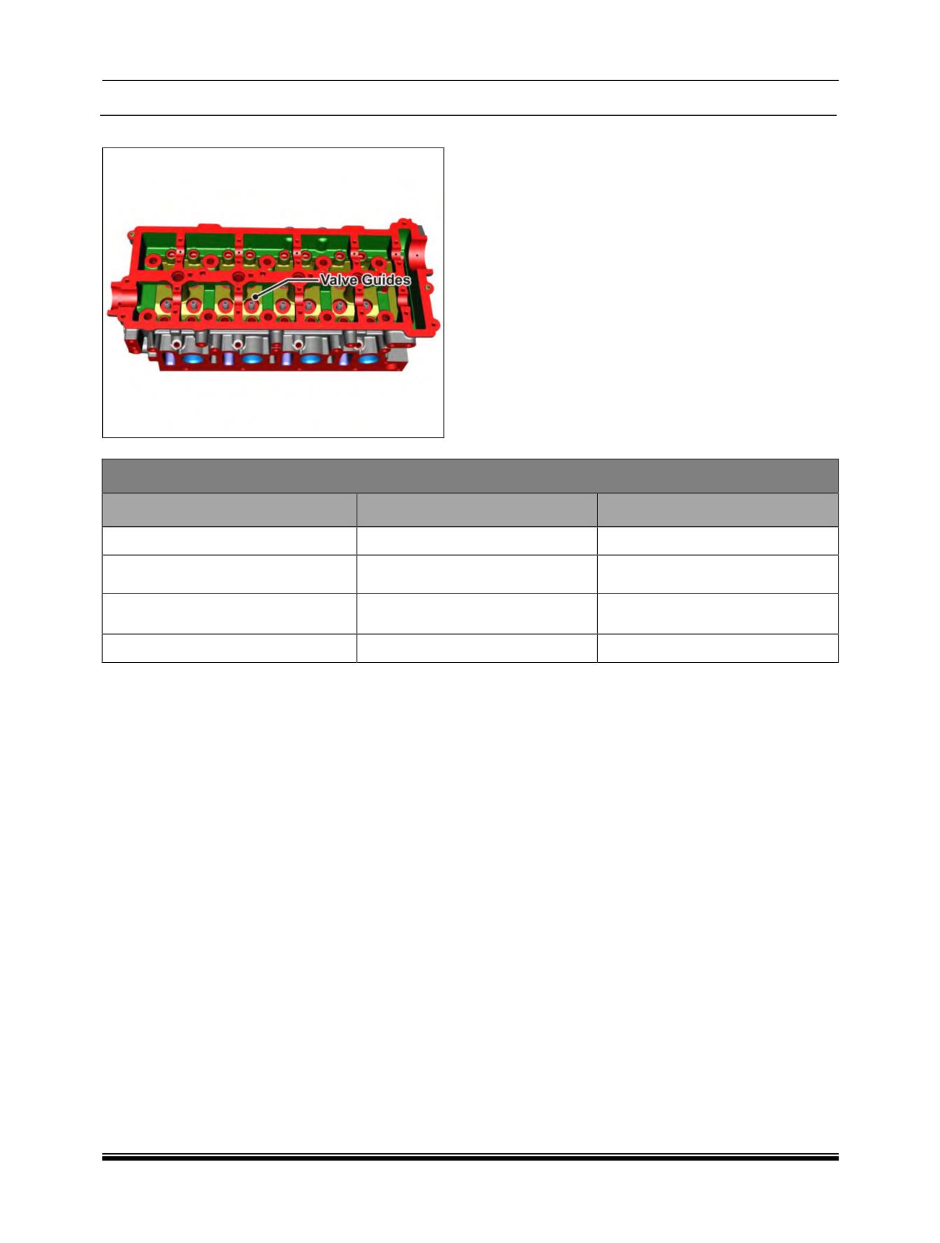
J. Valve Guides :
1. In case of valve stem sticking in valve guide
bore or Excessive clearance between them,
remove valve guide From cylinder head using
drift (Part No.2868 5890 06 05).
2. Check the condition of valve guide oil seals.
3. Check valve guide bore diameter in cylinder
head and if necessary, ream valve guide bore
in cylinder head to next over size.
4. Install matching size valve guide in cylinder
head using drift (Part No. 2868 5890 06 05)
and spacer (Part No. 2653 5890 06 01).
5. Fit Valve guide oil seals.
Valve Guide Specification
Dimension
Normal
Normal 1
Valve Guide Bore in Cylinder Head
Ø 10
+ 0.04/ + 0.023
Ø 10.25
+ 0.04/ + 0.023
Valve Guide O.D.
Ø10.0 x 6
+ 0.043/ + 0.034
Ø10.25 x 6
+ 0.051/ + 0.040
Valve Guide I.D.
5.4
5.4
Valve Guide Length
45.5
(Inlet/Outlet)
45.5
(Inlet/Outlet)
Note :
Valve Guides and Valve Seats are separately not serviceable. They come along with the cylinder
head as an assembly.