


 330 / 1906

ENGINE
96
6. Rotate FIP gear to align hole on the FIP
mounting bracket and lock with locking pin
(Part
no. 2653 5890 06 07).
7. Rotate Camshaft and lock the position with
camshaft locking plate (Part no. 2653 5890 06
09).
8. Locate Camshaft pulley on to camshaft front
end and assemble washer and bolt. Keep the
camshaft bolt finger tight.
9. Fit the Touch idler with specified fastener and
tightened with specified torque (2.5±0.3Kgfm).
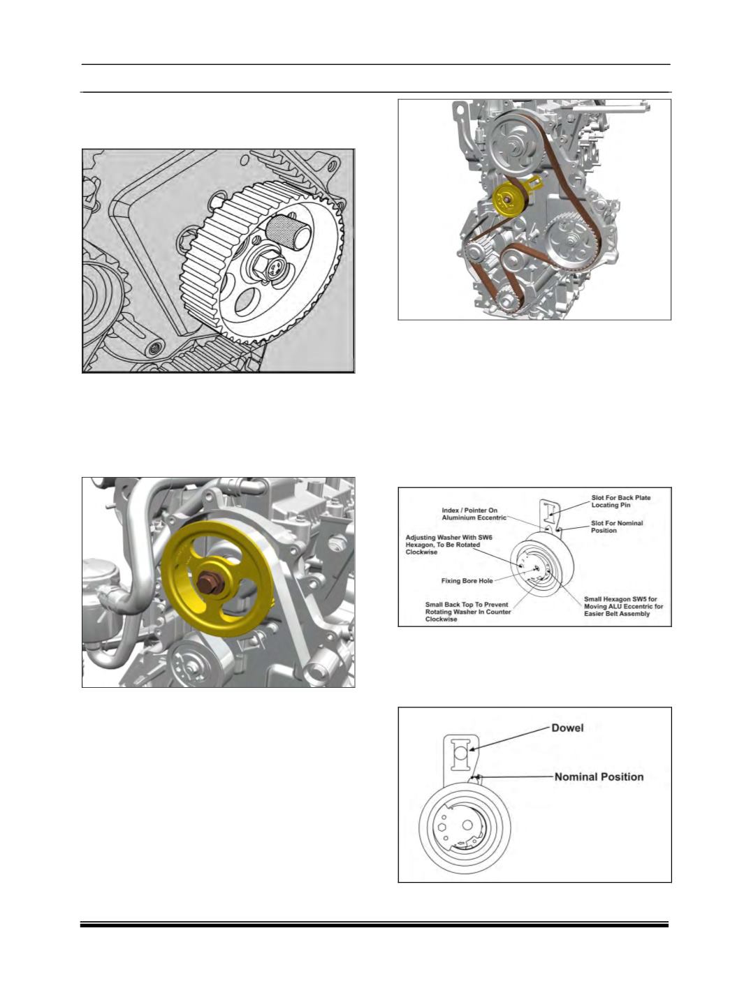
10. The Auto tensioner is installed onto engine
after preassembly of timing belt, ensuring that
the location features (fork of the back plate
and dowel pin) of the back plate are aligned
correctly.
11. Loose fit the Auto tensioner, finger tighten or
0.3 – 0.6Kgfm torque through the fixing bore
hole during setting.
12. Position the timing belt on pulleys in order of
Crank pulley, Main idler, FIP, Touch idler,
Camshaft pulley, Tensioner and then Water
pump.
13. The adjusting washer has to be rotated in
clockwise direction by means of the Allan key
(SW6) whilst preventing the M8 nut from
turning by means of a tool. The aluminum
eccentric with pointer will start rotating during
the setting of the adjusting washer / eccentric.
The adjusting washer has to be rotated until
the pointer reaches a position about 10°to
15°from the nominal position in direction of
higher load (pointer on the right side of the
window).
14. The adjusting washer has then to be rotated
counter-clockwise until the pointer is aligned
according to the attached picture “Nominal
position” (pointer is aligned with the index
mark on the back plate).