


 1458 / 1906

ELECTRICAL
156
Diagnostics tool connection problem:
A) Steps to be followed to solve diagnostic
tool connectivity issue:
Do Ignition Off
Step 1.
Check Diagnostic tool communication
1. if K line based ECUs (FATC, TOC and
Airbag ECU only communicating) then check
CAN wired for resistance
2. If only CAN based ECUs (xxxxx) are
communicating - then check K line wire
continuity from OBD II connector pin no 7
(TBC) to IC Pin noxx(TBC)
3. If above is ok, and if all ECUS are not
connecting through tool then check
Diagnostics Fuse in cabin fuse box (5A), if
found faulty.
4. if still not working then, check installation so
the SAMTECK drivers and TML diagnostics
tool installations in service Laptop /
computer.
B) If still there is diagnostic tool connectivity
issue:
1. Check CAN resistance between -
a. Measure resistance of vehicle CAN bus
between PIN no 8 (CAN H) and PIN No 9
(CHA L) in OBD connector. If resistance is
60 Ohm (+/- 5Ohm), then bus is OK.
b. Measure resistance of diagnostics CAN bus
between PIN no 6 (CAN H) and PIN No 14
(CHA L) in OBD connector. If resistance is
120Ohm (+/- 10Ohm), then bus is OK.
Measure resistance between CANH and
GND, CANL and GND:
If resistance is in ~ K-Ohm, then no short
circuit between the wires.
If it is less than 10 Ohm, there is short
circuit between the two wires
2. Measure resistance between CANH and Batt,
CANL and Batt
If resistance is in ~ K-Ohm, then no short
circuit between the wires.
If it is less than 10 Ohm, there is short
circuit between the two wires
3. Check continuity between IPC CAN_H (pin no.
6) vehicle side connector to OBD connector
CAN_H (pin no. 6) and CAN_L (pin no. 14)
vehicle side connector to ODB connector (pin
no.14).
4. Fix the failures in harness
CAN termination Module introduction
The Termination module is required as a
separate external module in the CAN network in
case internal termination resistor is not present in
ECU. The termination module is located in the
cabin fuse box. The termination module is
present in the following vehicle variants as
follows:
1. XE variant – termination module is present in
Vehicle CAN
2. XT variant – termination module is present in
ESP private CAN
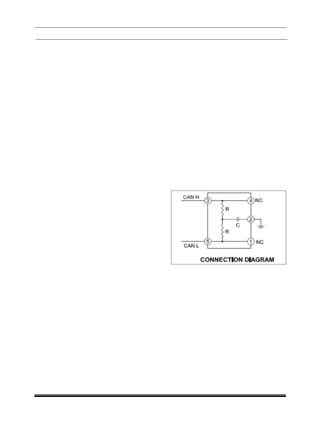
CAN termination Module Electrical details
The termination module has a resistance value of
~120 Ohms. This can be measured between pin
no 3 (CAN H) and pin no 5 (CAN L).
Diagnostic Test of Termination module
The CAN network can be affected if the
termination module is damaged or disconnected
from the CAN bus. In case CAN Bus Off or CAN
open circuit failure DTC is observed, one
probable cause could be that CAN termination
module is disconnected/damaged. For this to be
verified, check if CAN bus termination resistance
is approx. 60 Ohms. If the resistance value is not
correct then proceed to verify the termination
module resistance.
Remove the termination module from the Cabin
fuse box and measure the termination resistance.
It should be 120 Ohms. Refit the termination
module in the cabin fuse box and check if the
vehicle CAN termination resistance is showing 60
Ohms. If issue is still present, then proceed to
check other areas like CAN lines are short
circuited etc