


 1198 / 1906

Anti-lock Braking System(ABS)
8
2. Pressure Reduction Phase :
If the ECU detects that the % Slip relative to the
other wheels and vehicle reference speed is still
increasing during the pressure hold phase and the
wheel is tending further towards lock, it will start
the pressure reduction phase, as the existing
brake pressure in the wheel brake is too high. It
will activate the relevant outlet valve within the
hydraulic modulator, switching it from its normally
closed position to open. This will allow fluid to
pass from the wheel brake into the accumulator
chamber within the modulator. At the same time
the ECU will activate the return pump integrated
into the modulator to draw fluid from the
accumulator and wheel brake and return it to the
TMC. This fluid being returned to the TMC is what
is felt as the pulsations at the pedal, and the
amplitude of the pulsations is relative to the
amount of fluid that needs to be reduced.
Pressure reduction will continue until the
controlled wheel speed returns to the vehicle
reference speed.
Solenoid
valve
Electricity
status
Valve
open-
close
Open-close
channel
INLET
ON
CLOSE
Master cylinder
-Wheel
cylinder
OUTLET
ON
OPEN
Wheel
cylinder -
reservoir
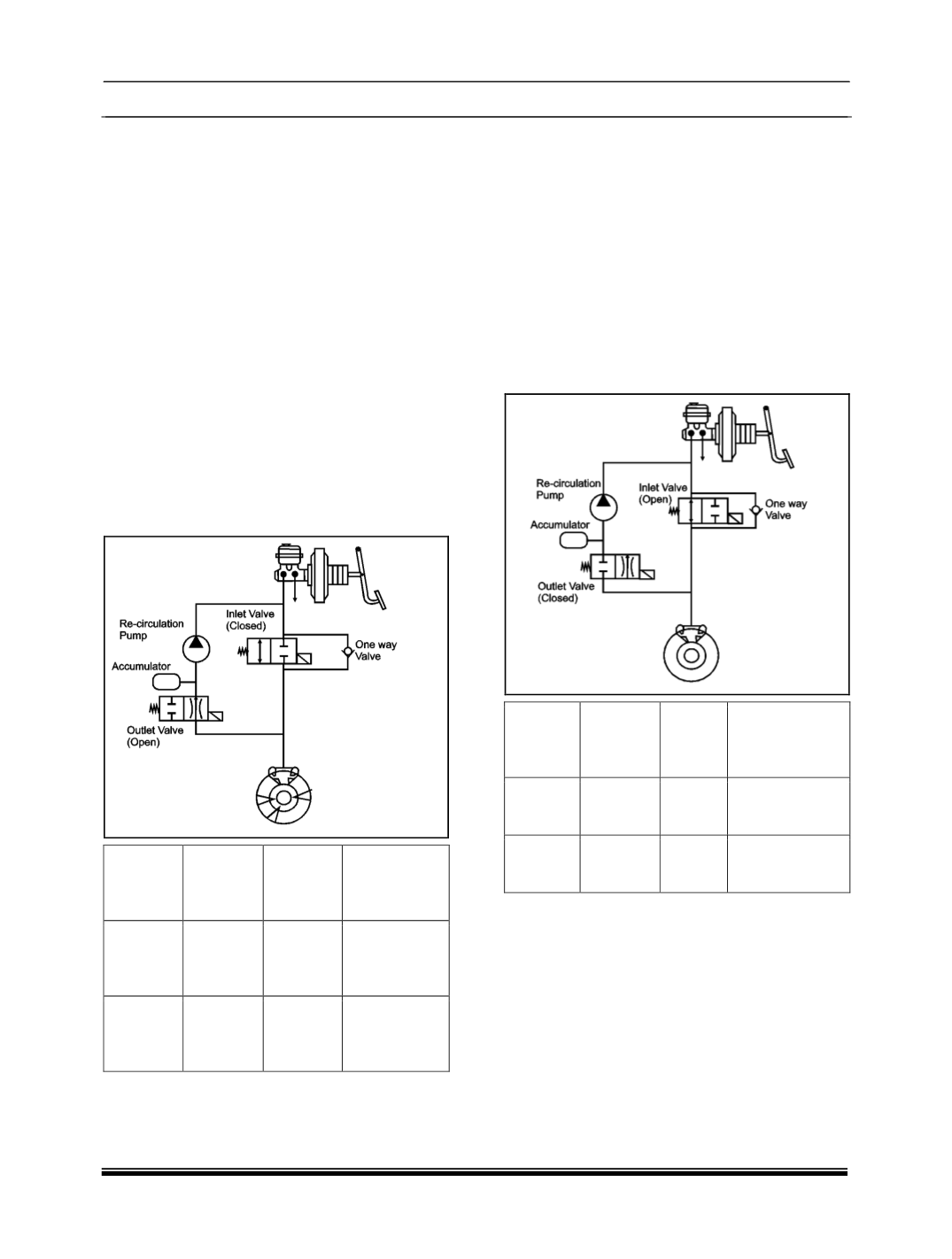
3. Pressure increase Phase :
As the ECU detects that the speed of the
controlled wheel has increased to the vehicle
reference speed and hence the % slip reduced. It
will sequentially deactivate the outlet and inlet
valves switching them to their normal positions.
With the outlet valve closed further pressure
reduction is prevented and the inlet valve can be
opened to allow brake fluid from the TMC to enter
the wheel brake increasing the brake pressure
once again. If the driver releases the brake at any
time during ABS control the inlet valves will be
deactivated and fluid can return to the TMC via
the inlet valve and the one way valve.
Solenoid
valve
Electricity
status
Valve
open-
close
Open-close
channel
INLET
OFF
OPEN
Master cylinder -
Wheel cylinder
OUTLET
OFF
CLOSE
Wheel cylinder -
reservoir