


 496 / 1863

ENGINE
64
B. Blow By System
:
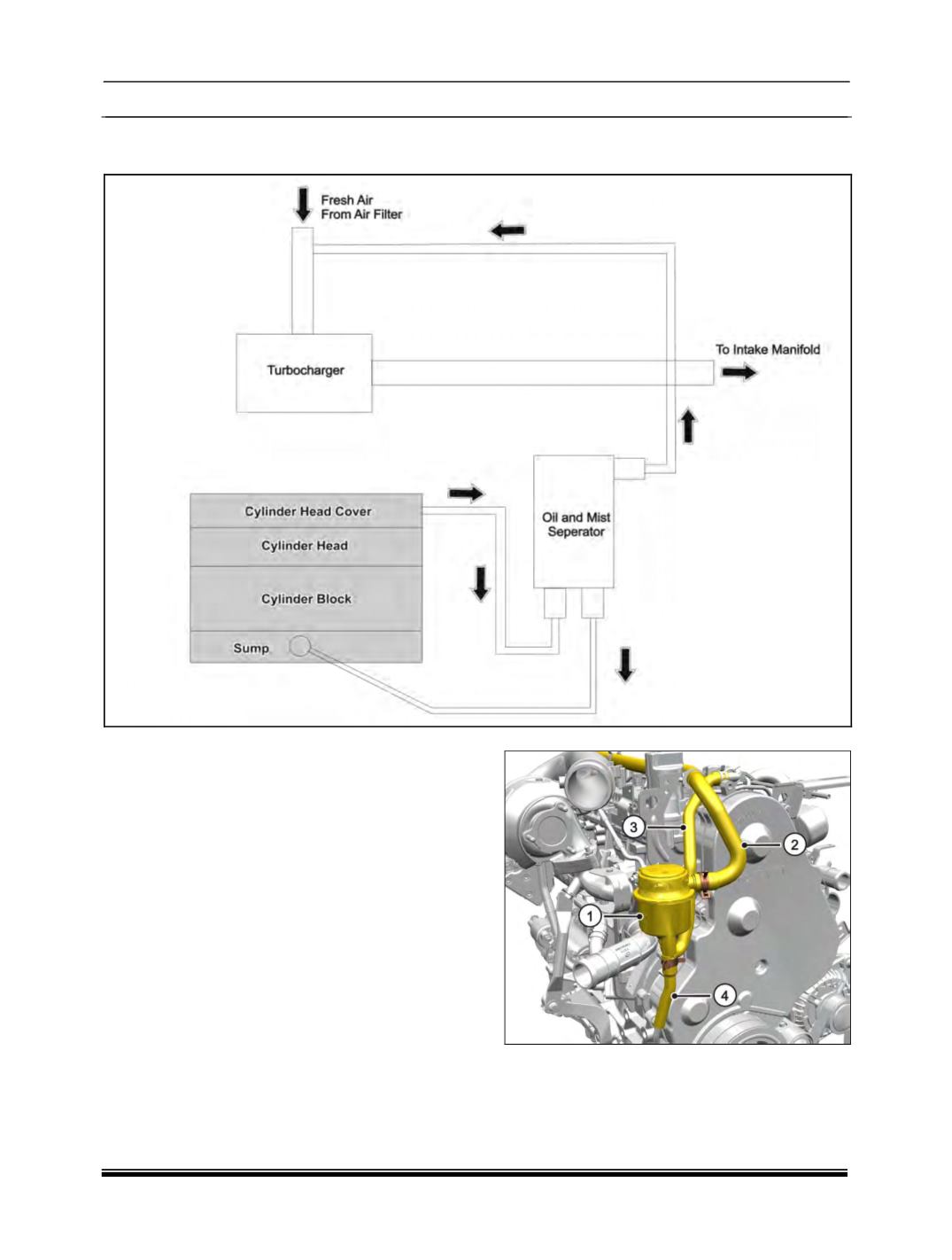
Blow By Circuit Schematics Layout :
In order to reduce the blow by gas emission, the
blow by gas is directed to the intake manifold
through the oil mist separator which separates the
oil from the blow by gas and allows the air to pass
to the intake manifold.
Blow by gases are drawn from crankcase and
cylinder head cover.
Components :
a) Oil Mist Separator :
The oil mist separator separates oil from the blow
by of the engine and sends it back to engine oil
sump. The remaining air and other gases are sent
to the inlet manifold.
There is a spring loaded diaphragm valve
provided on the oil separator outlet which
prevents the flow of excessive blow by gasses
from the oil separator to the inlet manifold in case
the air filter is chocked and high suction starts
acting on outlet port of oil separator.
1. Oil Mist Separator.
2. Hose to Inlet Pipe
3. Hose from cylinder head cover
4. Hose from oil sump
No leakage past diaphragm or top cover of oil
separator is permitted. Replace the assembly if
there is any leakage or found defective.