


 438 / 1863

ENGINE
6
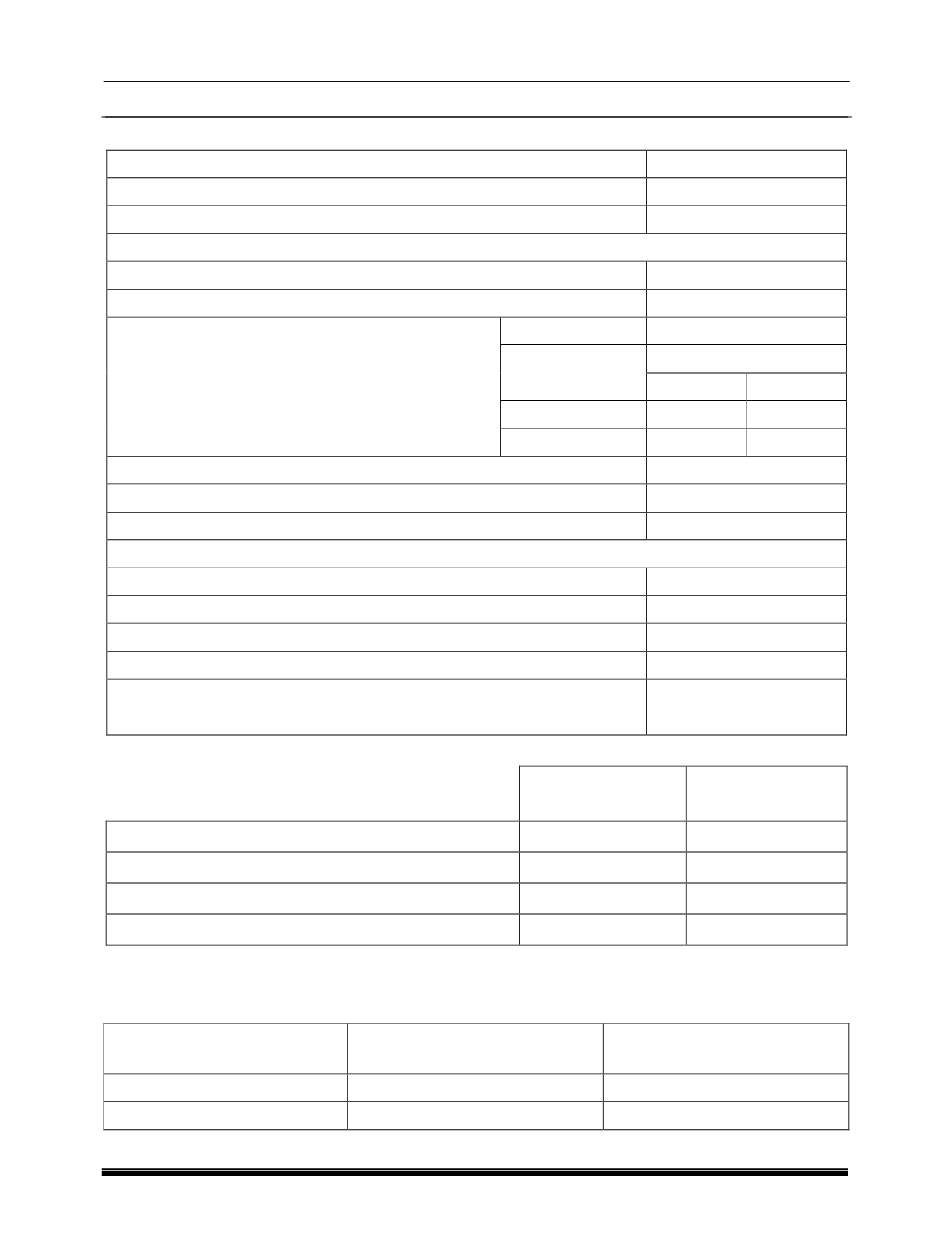
E. ASSEMBLY CLEARANCES:
Description
Values (mm)
Main Bearing Clearances (Without Expansion) M/S FEDERAL MOGUL
0.026 to 0.085
Main Bearing Clearances (Without Expansion) M/S BIMENTAL
0.026 to 0.077
Connection Rod Clearance – Big End (Without Expansion)
0.013 to 0.067
Connecting Rod Axial Play (Big End)
0.1 to 0.35
Piston Projection On Cylinder Block
(Max. Difference In Piston Projection Between Any
Two Pistons In A Clock Should Not Exceed – 0.12mm)
Projection
Gasket Thickness
0.56 to 0.64
Identification
1.3
1 Notch
0.65 to 0.73
1.4
2 Notches
0.74 to 0.82
1.5
3 Notches
Piston Skirt to Cylinder Bore Radial Clearance (On Thrust Side)
0.032 to 0.042
Crankshaft Axial Play
0.070 to 0.252
Connecting Rod Small End Bush Clearance
0.020 to 0.039
Camshaft Bearing Clearance
0.02 to 0.062
Camshaft Bearing Axial Play
0.18 to 0.25
Valve Stem Clearance, Inlet
0.02 to 0.046
Valve Stem Clearance, Exhaust
0.040 to 0.066
Camshaft to Finger Follower Clearance, Inlet
0
Camshaft to Finger Follower Clearance, Exhaust
0
Valve Timings:
Valve Timing
At 0.05 mm valve lift
Valve Timing
At 1 mm Valve Lift
Inlet Opens
11
0
(B.T.D.C)
11
0
(A.T.D.C)
Inlet Closes (A.B.D.C)
36
0
8
0
Exhaust Opens (B.B.D.C)
39
0
17
0
Exhaust Closed
11
0
(A.T.D.C)
17
0
(B.T.D.C)
Notes:
Assembly Clearances Values and Valve Timings are for reference only.
Complete engine to be leak tested with air.
Region
Pressure
Leakage
(cc/min) Max.
Air Side
0.125 bar
100
Water Side
0.7 bar
10