


 1624 / 1863

ELECTRICAL
322
Circuit diagrams are arranged so that current
flow is from top of the diagram (
Power source
) to
the bottom of the diagram(ground
).
The circuit
diagrams are presented with Power distribution
first, followed by individual circuits for each
electrical system on the vehicle.
Power Distribution
The Power Distribution diagram shows the
connections from the battery to the Battery
distribution unit & from battery distributions unit to
Main distribution unit and cabin fuse & relay box.
Wire attributes
Additional information is shown alongside wire
1. Wire colour:
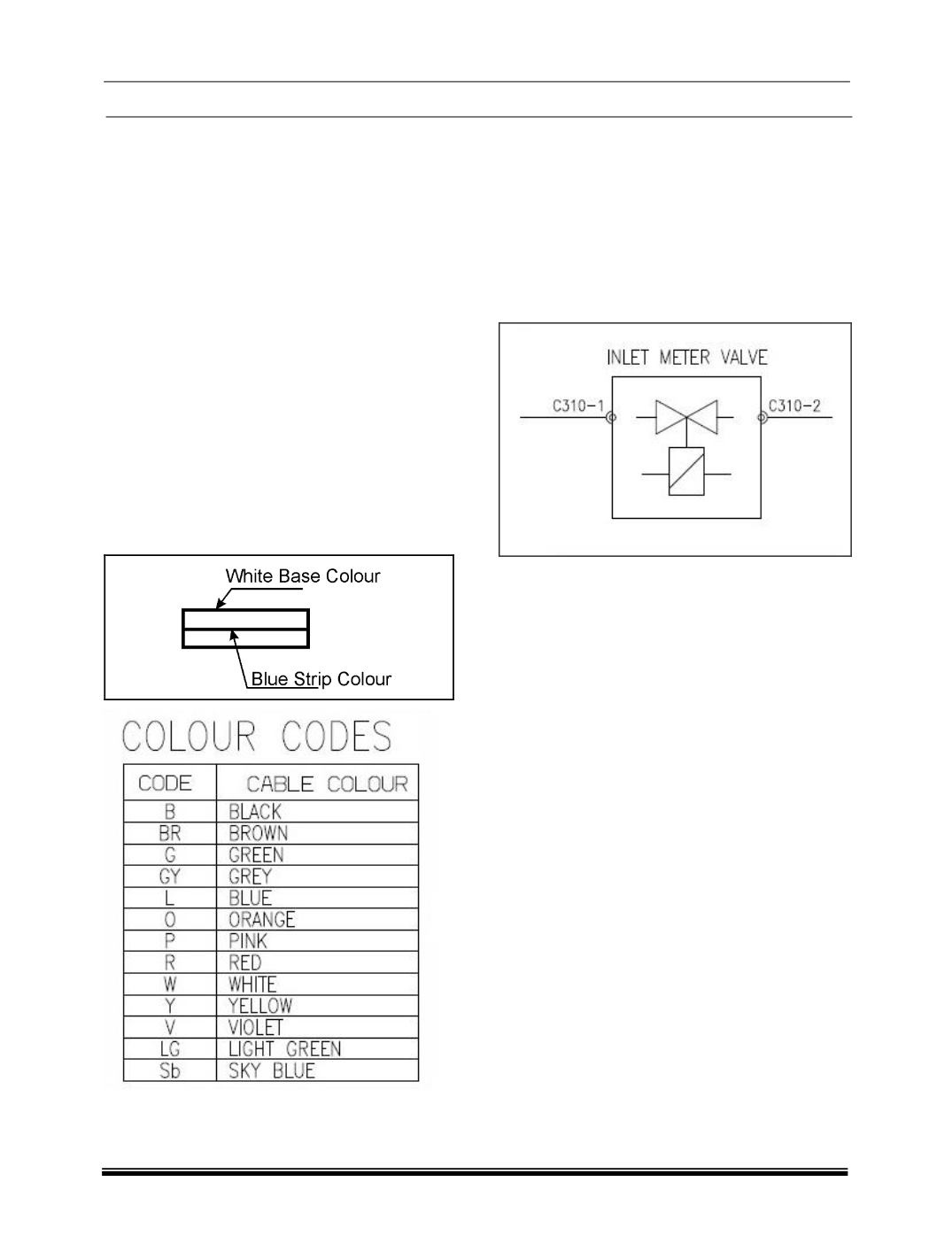
There are two kinds of coloured
wire used in this vehicle. One is single coloured
wire & other is dual coloured (striped) wire. The
single coloured wire uses only one colour symbol
(e.g. “W”). The dual coloured wire uses two colour
symbols (e.g. W-L) the first symbol represents the
base colour of the wire (i.e. “W”) & second symbol
represents the colour of the strip (i.e. “L”).
2.
Wire gauge -
the cross- sectional area of the
wire in square millimeters. This is included to help
the technician to select the correct wire during
harness repair.
Components
Each component represented with his description
& connector no.
E.g. Description of component - Inlet metering
valve & connector No.H-13