


 441 / 1232

ENGINE 1.3L QUADRAJET (90PS)
104
(v)
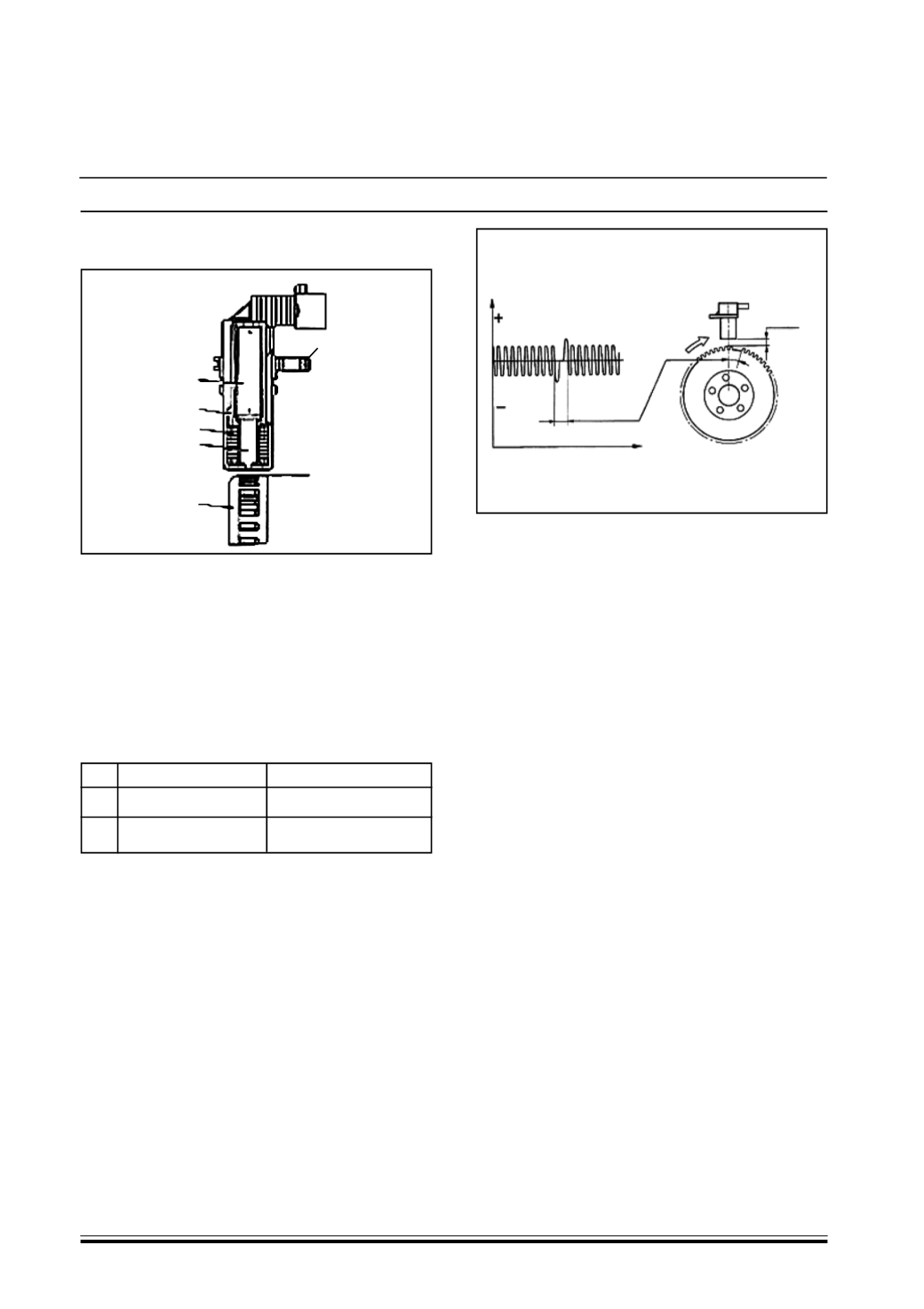
0.8+1.5 mm
(a)
CONSTRUCTION
1. Brass bush
2. Permanent magnet
3. Plastic sensor casing
4. Coil reel
5. Polar core
6. Ring gear or flywheel
PIN OUT
Pin Description
Signal type
1 Flywheel signal (A) Frequency output
2 Flywheel signal (B) Frequency output
TECHNICAL SPECIFICATIONS
Winding resistance 790 Ohm +/- 20%
Winding resistance 680 mH +/- 20% (f=1khz)
The recommended distance (gap) between the end
of the sensor and the flywheel for obtaining correct
signals should be 0.8 - 1.5 mm.
This distance is not adjustable. If the gap is found to
be outside the tolerance limits, check the condition
of the sensor and phonic wheel.
The graph shows the sensor output signal in relation
to the horizontal development of the fly wheel.
OPERATION
The changeover from full to empty determined by
the presence or absence of a gap brings about a
magnetic flux change sufficient to generate an
induced alternating voltage proportional to the
number of teeth on the ring (or phonic wheel).
The frequency and amplitude of the voltage send to
the electronic control unit provides the latter with an
indication of the engine angular speed.
C.Cam angle sensor
Specifications
This Hall effect sensor is fitted on the camshaft
housing facing the camshafts.
A tooth on the pulley allows the timing sensor to
indicate engine timing position.
The injection control unit uses the timing sensor
signal to recognize T.D.C. at the end of the
compression and during starting to synchronize the
engine management control unit with the engine.
The sensor is fitted by the exhaust side camshaft.
2
3
4
5
6
1