


 310 / 1232

ENGINE 1.3 QUADRAJET (75PS)
85
3.1.7 EXHAUST SYSTEM
A. DESCRIPTION
The Exhaust system of 1.3 Quadrajet consists of a
Catalytic converter, Lambda Probe and EGR with heat
exchanger other than the other conventional
components like Exhaust Manifold, silencer, etc.,
B. COMPONENTS
CATALYTIC CONVERTER
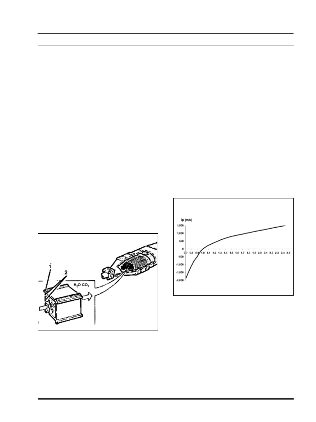
The catalytic converter is a post-treatment device for
oxidizing the CO, HC and particles transforming them
into carbon dioxide (CO
2
) and water vapour (H
2
0).
The catalytic converter consist s of a ceramic,
honeycomb structure (1) with cells impregnated with
platinum (2) which catalyzes the oxidation reactions.
The exhaust gases p assing through the cells heat
the catalyzer triggering of f the conversion of the
pollutants into inert compounds.
The oxidizing chemical reaction of the CO, HC and
particles is effective at temperatures of between 200
and 350°C.
In effect, above 350°C the sulphur cont ained in the
diesel fuel starts to oxidize producing sulphur dioxide
and sulphur trioxide.
LAMBDA PROBE
The linear “UEGO” planar type Lambda sensor is fitted
on the catalytic converter and informs the engine
management control unit of the combustion progress
The sensor is an oxygen sensor containing two
comparative cells that make it possible to measure ë
values (ratio between the quantity of int ake air and
the theoretical quantity of air required for the complete
combustion of the fuel injected) between a wide range
from ë = 0.7 (rich mixture) to the value in air (ë= (lean
mixture).
It is used to compare the reading of the air flow meter
with the one mapped in the control unit and, if
necessary, correct the fuel injection to be within the
emission limits.
The sensor works by comparing the concentration of
oxygen in the reference cell, housed inside the sensor,
with the combustion gas flowing inside the
comparison cell next to the reference cell. Depending
on the resulting imbalance, the engine management
control unit regulates a current signal (lp) that
rebalances the oxygen content in the comparison cell
through an electrochemical action. The value of lp is
proportional to the ë value measured according to the
graph illustrated below.
In order to activate the operation of the sensor quickly,
the sensor contains a heater operated in duty cycle
by the engine management control unit according to
a calibrated strategy.
The two comp arison cells and the heater are
incorporated in the same planar ceramic element
(layers of several ceramic elements) in order to keep
the structure compact and guarantee high response
and heating speeds for the actual element.
HC-CO-C