


 205 / 1232

Revotron 1.2T
158
Connector View :
Component Specification :
The ignition coil is mounted on thermostat
housing, to have the shortest length of high
tension cable connected to spark plugs so as
to reduce the level of electromagnetic
radiation from HT cables and possible
interference to ECU. The ignition coil
assembly - a duel spark coil with built-in
power switch with a 4 pin connector operates
on conventional principle of secondary
voltage generation due to induction. The
primary switching (ON/OFF) is triggered by
ECU which maintain constant dwell time, i.e.
time required to energize primary coil,
throughout the operating condition. An
ignition coil
(also called a
spark coil
) is an
induction coil in an automobile's ignition
system which transforms the battery's low
voltage to the thousands of volts needed to
create an electric spark in the spark plugs to
ignite the fuel. The wire that goes from the
ignition coil to the distributor and the high
voltage wires that go from the distributor to
each of the spark plugs are called spark plug
wires or high tension leads.
Sensor Stand alone Diagnosis :
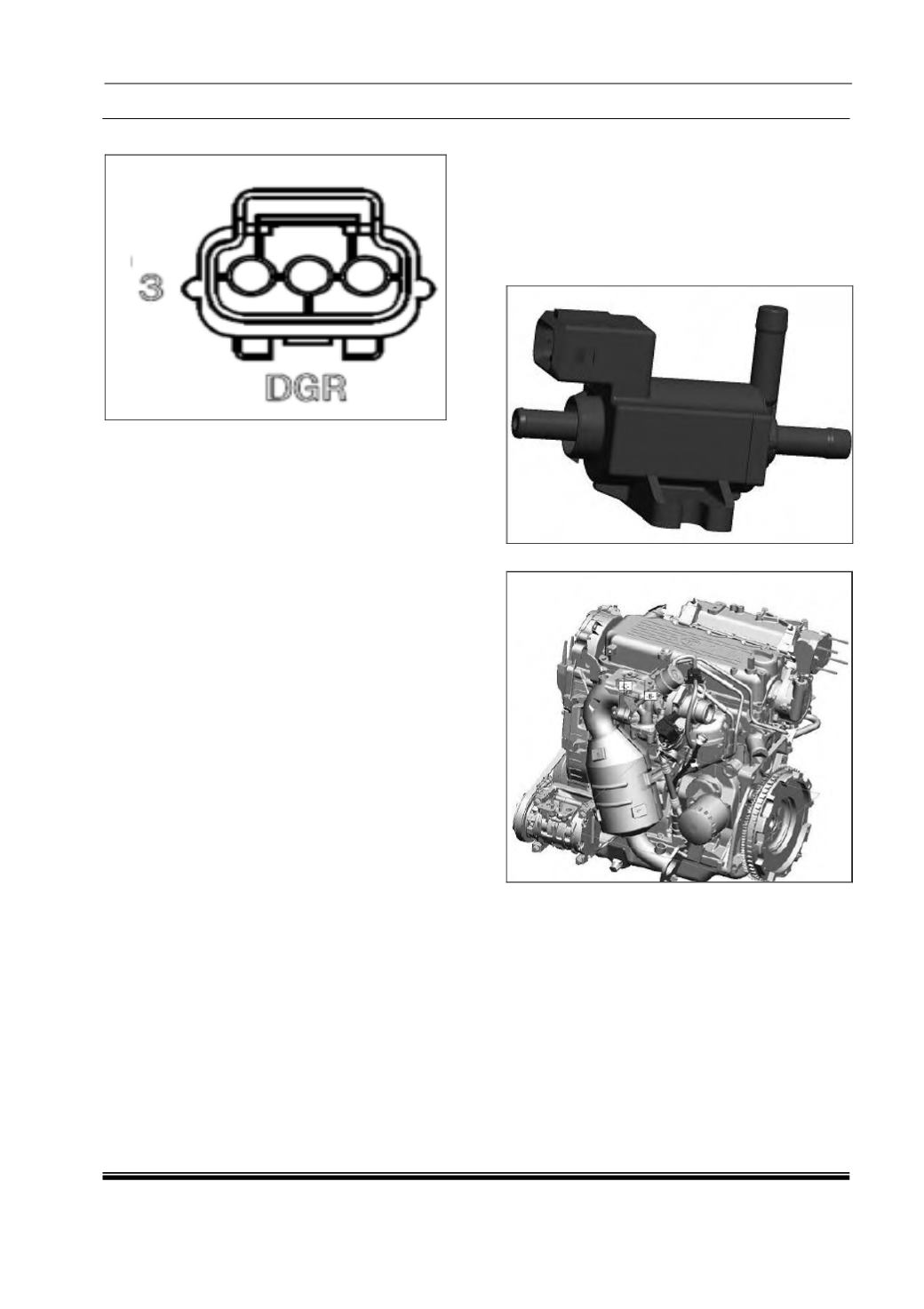
Connector details
1. ECU pin M1G3 : (cylinder 1 and 4)
2. ECU pin M1H3 : (cylinder 2 and 3)
3. Supply voltage (12V)
4. Ground (through solenoid)
Use multimeter to check primary coil
resistance between pin 4 and pin 2 (cylinder 3
and 2), or pin 4 and pin 1 (cylinder 1 and 4),
which should be 0.6ohms.
ii. WG PWM actuator :
Component Details :
Turbocharger bypass valve is a solenoid
valve, whose magnetic coil is energized to
open the valve. Valve can be opened in any
position between its 0% opening to 100%
opening by controlling the magnetic coil
energization.
Component Location :
Preliminary Checks :
1. Loose/ Damaged Connections between
bypass valve and EMS ECU.
2. Check for back out of pins at both bypass
valve connector and ECU connector.
3. Check for damage of pins at both bypass
valve connector and ECU connector.
4. Check the continuity bypass valve
connector pins to the ECU pins.
5. Check whether the bypass valve is getting
main relay power supply.