


 161 / 1232

Revotron 1.2T
114
iii. Fitment of Cylinder Block Sub-Assemblies
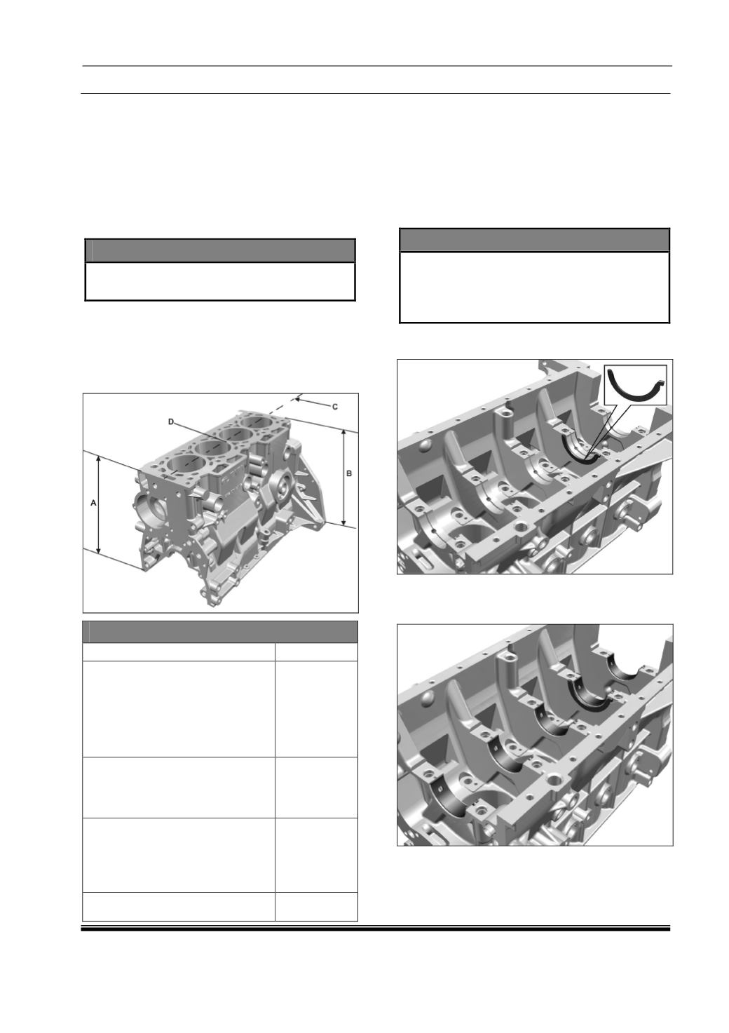
Cylinder Block
1. Check cylinder block for cracks by pressure
testing method. Clean cylinder bores, bearing
surfaces, oil passages in crank case
thoroughly. Check water jackets for leakages
by blowing air at a pressure of 5 bar & then
dipping the cylinder block in the hot water.
(Temp of water 70
0
to 80
0
C)
NOTE
•
The block with any leakages / cracks
should be discarded.
2. Check crankcase mating surfaces with
cylinder head for unevenness with the help of
straight edge and feeler gauge. If necessary
grind this surfaces just to clear unevenness.
Measure across the length and breadth to
specific mention value in table.
Dimension (mm)
Height of cylinder block (A & B)
265.8/265.6
Maximum permissible
unevenness of cylinder block
case mating surface with
cylinder head 150 X 150
Cross wise (D)
Length wise (C)
0.015
0.030
Maximum permissible out of
parallelism between crank case
top and bottom machined
surface.
0.2
Maximum permissible shift in
perpendicularity of cylinder bore
from crank shaft axis when
checked from crank shaft center
line
0.25
Maximum permissible taper and
sphericity of cylinder bore
0.007
3. Ensure main bearing parent bore dimensions
are within specified limits. (For specified limit
and procedure refer cylinder block inspection
chapter.)
4. Ensure that the minimum height of crank case
is not less than the specified minimum height.
NOTE
•
Apply light coat of grease to the fourth
main bearing cap.
•
Ensure the slot on thrust washers are
facing on outer side.
5. Install thrust washers in crankcase at their
respective locations on 4
th
main bearing.
6. Place lower bearing shells and ensure the
locking slot on bearing shells are properly
fitted.