


 801 / 1236

ELECTRICAL
23
ELECTRICAL
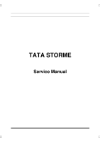
3.4 SREC assembly with DEF:
Align the marks previously made and insert the
stator winding into the drive end flange. Align the
marks and fit the slip ring end cover on the stator
winding in such way that six stator winding leads
pass through appropriate holes on the slip ring end
cover. Tighten the screw.
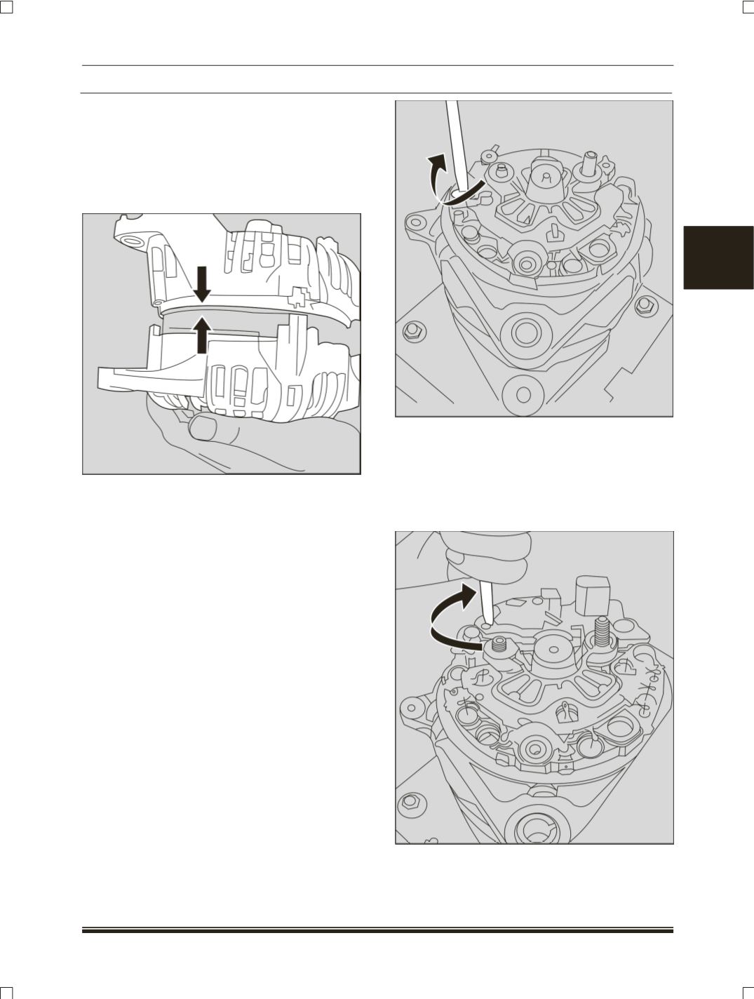
3.5 Rectifier Assembly:
Fit the rectifier on the slip ring end shield ensuring
that the six ends of the stator winding pass through
the appropriate plating sleeves of the rectifier.
Solder the six stator winding ends on to the
rectifier at the specific points. Fasten the rectifier
on the slip ring end shield with two screws.
3.6 Regulator assembly:
Install the voltage regulator on the slip ring end
shield by carefully inserting the carbon brushes
through the opening of the fitting ring. Tighten the
screws. Connect the rectifier and the regulator
using the screws.