


 426 / 1236

TRANSFER CASE
38
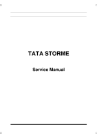
F. ASSEMBLY OF LOCK UP SHIFT ASSEMBLY
1. Slide both
(2W – 4W)
lock up assembly and
lock up fork downward in to output shaft.
2. Mount clutch housing on output shaft.
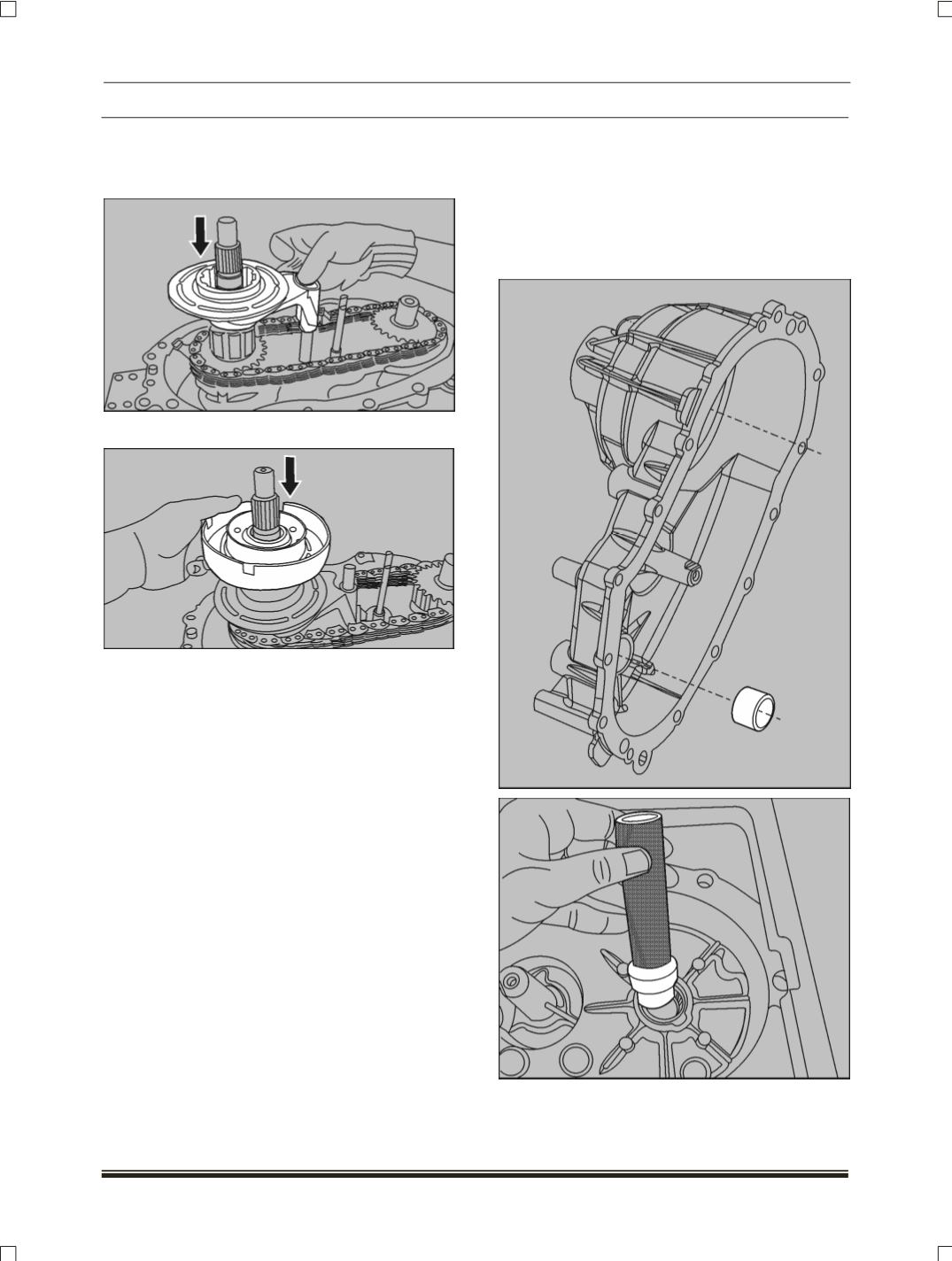
G. REAR COVER ASSEMBLY
1. Position the cover with the open end facing up
on the table.
2. Position the end of needle bearing with the
identification mark up and press drift (Part
no.2870 5890 26 05) into the cover
(If
removed)
.