


 133 / 1236

ENGINE
101
2.1.4 AIR INTAKE SYSTEM
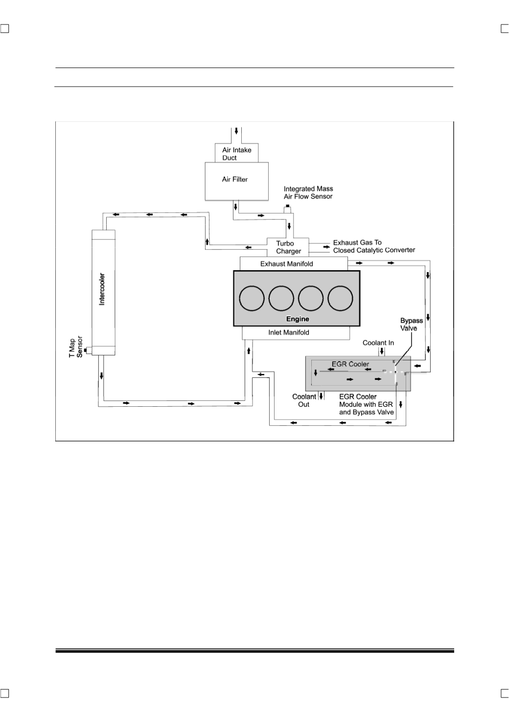
2.1.4.1 SYSTEM LAYOUT
Atmospheric air is drawn into the combus-
tion chamber through the air intake system as
shown in above schematic layout. The air intake
system should have the ability to supply sufficient
quantity of air to the engine.
The air is driven to the intake manifold pri-
marily due to the suction created by the engine. The
fresh air from the outside atmosphere is made to
pass through an air filter and into the turbocharger.
Here the air is compressed by the turbocharger
which is driven by exhaust gasses. It then passes
through the intercooler where temperature of the
compressed air is reduced and then into the com-
bustion chamber through intake manifold.
EGR cooler module with EGR and bypass
valve
(For Exhaust Gas Recirculation)
is used to
reduce the NOx emission levels. This assembly
comprises of EGR valve, EGR cooler and bypass
valve. A part of the exhaust gas is tapped from the
exhaust manifold and made to mix with the air com-
ing from the intercooler before entering the intake
manifold.
For more details on EGR cooler with by-
pass valve, refer Exhaust System.