


 642 / 1526

22
POWER STEERING
F) Fitting the housing cover
1 Fit the two round seal rings (42 and 43) in the
axial groove of the housing cover (40).
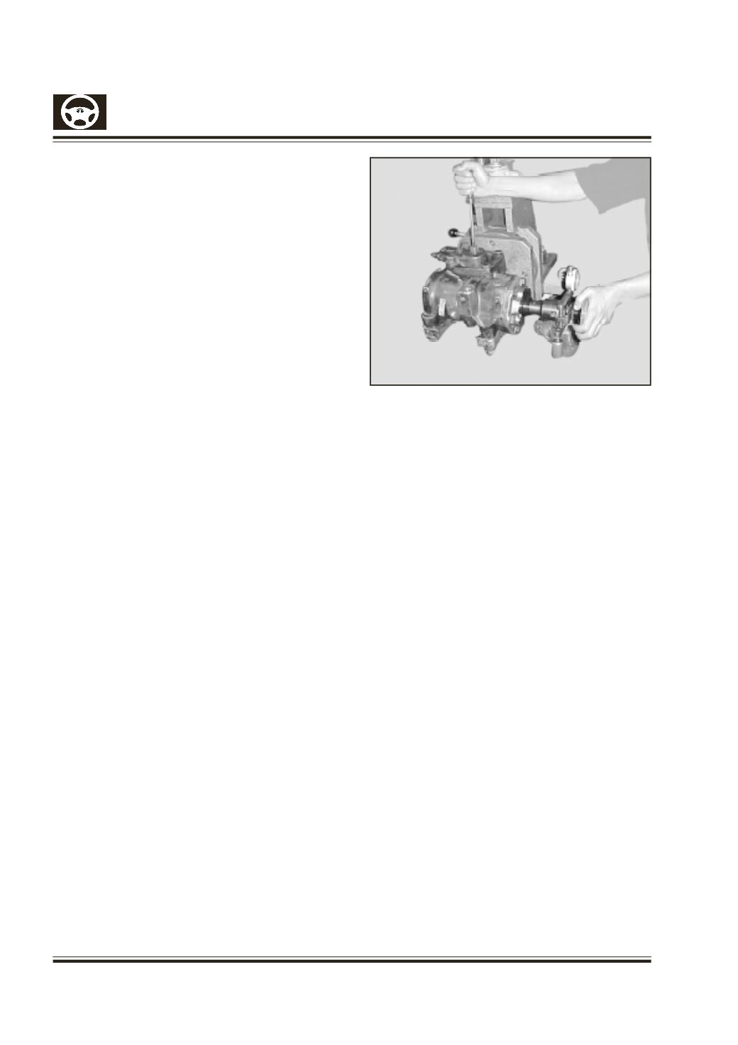
1.1 Fit the housing cover (Fig-11).Position the housing
cover by turning the adjusting screw (31) on the
front surface of the housing in a counter – clockwise
direction and screw on the sealing nut (50)
temporarily.
Screw in and tighten the hexagon bolts (46) with
washers (47).
Screw in the threaded plug (48) and tighten (refer
to the technical data for the tightening torque).
G) Setting the pressure Point
1. Place the torque measuring unit Tool No.4 and
insert Tool no.5 on the worm.
2. Turn the steering from the one end position to the
other. Measure the frictional force outside the
pressure point and determine the total turn of the
steering wheel.
3. Then set the frictional force in the area of the
pressure point (mid position; half of the total turn
of the steering wheel). The torque measuring
device is turned both to the left land right of the
center position and the adjusting screw should be
screwed out so far until an increase in the friction
torque of 40-60 Ncm compared to the value
measured in point 2 is set (Figure12) .
4. Tighten the sealing nut (50) (refer to the technical
data of the tightening torque), while holding the
adjusting screw in a fixed position. Check the set
torque once again. Fit the protective cap (70).
H)
.
Checking the frictional torque of the completely
assembled steering unit
Place the torquemeasuring deviceTool no.4 and insert
Tool no. 5 on the worm.Turn the steering unit form one
end position to the other.Measure that frictional torque
outside the pressure point in a horizontal position (refer
to the technical data.)
Functional test:
Clamp the completely assembled steering unit on the
steering test rig according to the instructions given in
section VII. Bleed the steering unit (see section II)
and increase the oil temperature to approximately
50
o
C.
Fig. 12
The adjustment values given in section VII are valid
for setting pressure point of the steering system after
completion of the repairs on the workbench. There is
no oil in the steering unit.
1. Testing the maximum pressure:
Block the steering unit in the mid position. Turn the
steering wheel until the maximum pressure has built
up on one side of the cylinder. For this purpose it is
necessary to apply a force of 100-200N (10-20 kg) to
the periphery of the steering wheel so that the
maximum path of the valve is utilized.
If the steering unit has no pressure limiting valve then
the pressure limiting valve built into the testing rig
must be set to the rated pressure which is
predetermined for the steering unit (this would
correspond to the rated pressure which is given on
the type plate of the pump).
The same measurements are now carried out in the
opposite direction of the steeringwheel. If themaximum
pressure is not reached within the specified tolerance,
the oil leakage in the steering system is too high.