


 632 / 1526

12
POWER STEERING
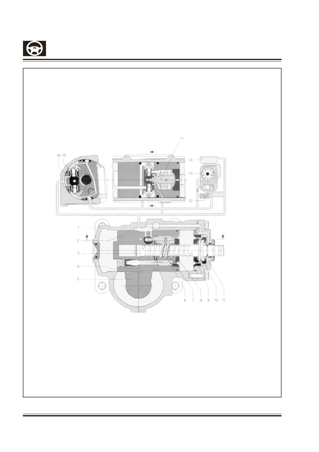
9 Threaded ring
10 Angular ball bearing
11 Cover
12 Pressure limiting valve
13 Vane pump with flow limiting valve
14 Oil Reservoir
15 Feedback piston (Hydraulic Reaction)
16 Valve piston
17 Driver
1 Housing
2 Piston
3 Worm
4 Bending Bar
5 Sector shaft
6 Balls
7 Steering nut
8 Threaded ring
Fig.1 SECTION VIEW of a ball
and power steering gear with
vane pump connected to it,
steering valve in neutral position.
Centering of the steering valve
by bending bar.
OIL FLOW : after flowing through
supply and return flow control
edges to the middle of the valve
spool and through bores to the
right and left cylinder Chamber,
the oil goes through respective
bores to a recess on the piston
top, from here back to the oil
tank.
Fig. 1 Steering valve in neutral position