


 457 / 1526

32
REAR AXLE
Fig. 64
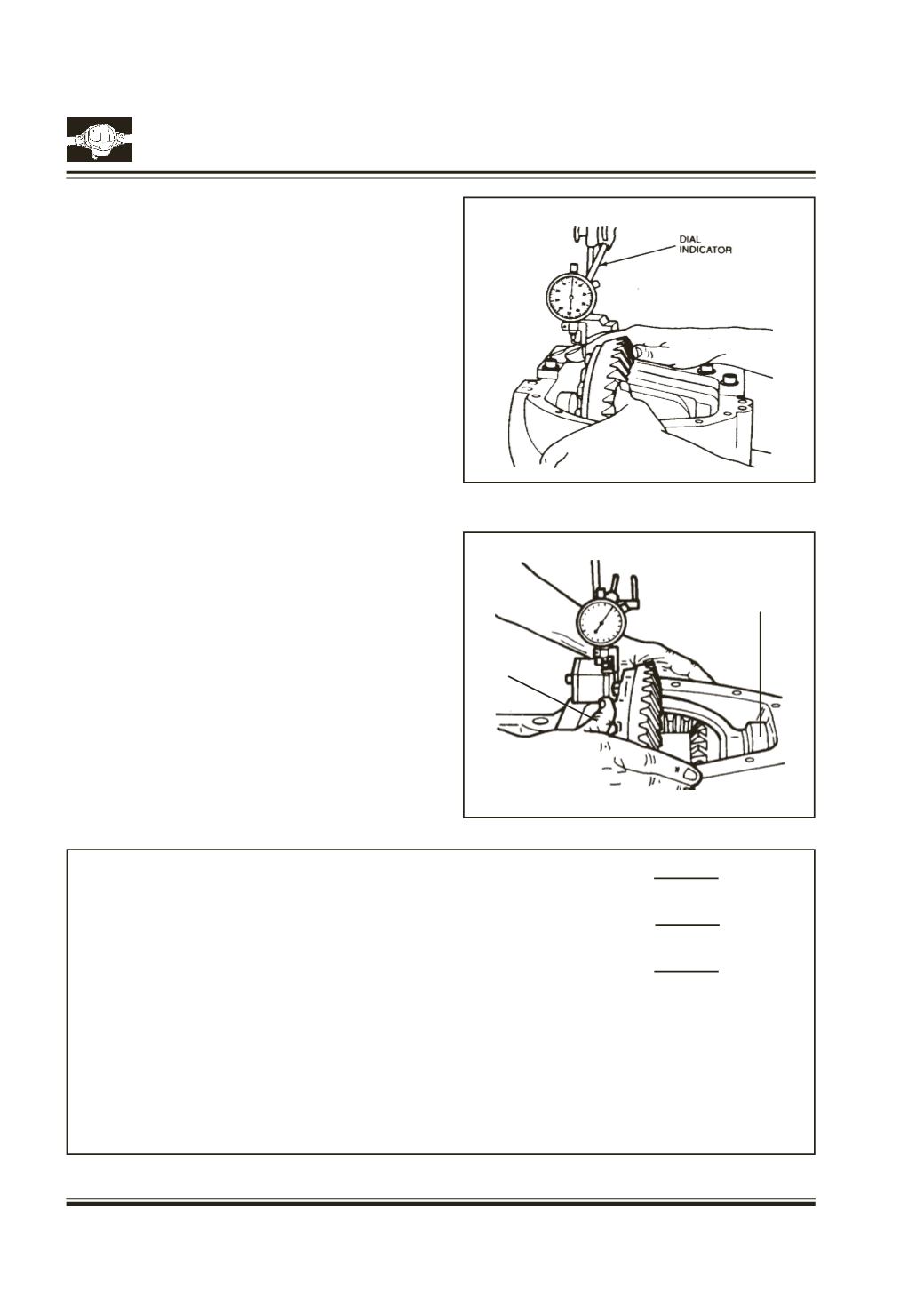
Fig. 63
Assemblemaster differential bearing
Pt.No. 2698 5890
3514 on to case hubs.
Place differential assembly into housing. Install dial
gauge and locate tip of indicator on the surface of
one of the ring gear screws.
Force the differential case assembly away from the
pinion gear. With force still applied set indicator at 0
(Zero).
Fig. 63
Force the differential case assembly and ring gear
to mesh with the pinion gear. Fig. 64
Rock ring gear to allow the teeth of the gear to mesh
repeat to obtain a stable reading. Record in given
format as B.
Fig. 63
Remove indicator and master differential bearings.
WORK SHEET FOR CALCULATION RING
GEAR BACKLASH AND DIFFERENTIAL
BEARING PRELOAD SHIMS
1. Total amount of space
Measurement
A
measured without ring gear.
2. Total amount of space
Measurement
B
measured with gear set assembled in carrier.
3. Measurement A minus
Measurement
C
Measurement B.
Assemble the shim pack using the figures determined in A, B & C adjusting the packs as described
below.
RING GEAR SIDE:
Assemble shim pack to measurement
B
- 0.125 mm. or
B
– 0.005"
OPPOSITE SIDE OF RING GEAR:
Assemble shim pack to measurement
C.
Add 0.20 mm or
C
+0.008"for differential bearing preload and backlash.
Ring Gear Side
Opposite Side of
Ring Gear