


 1366 / 1526

PROPELLER SHAFT
13
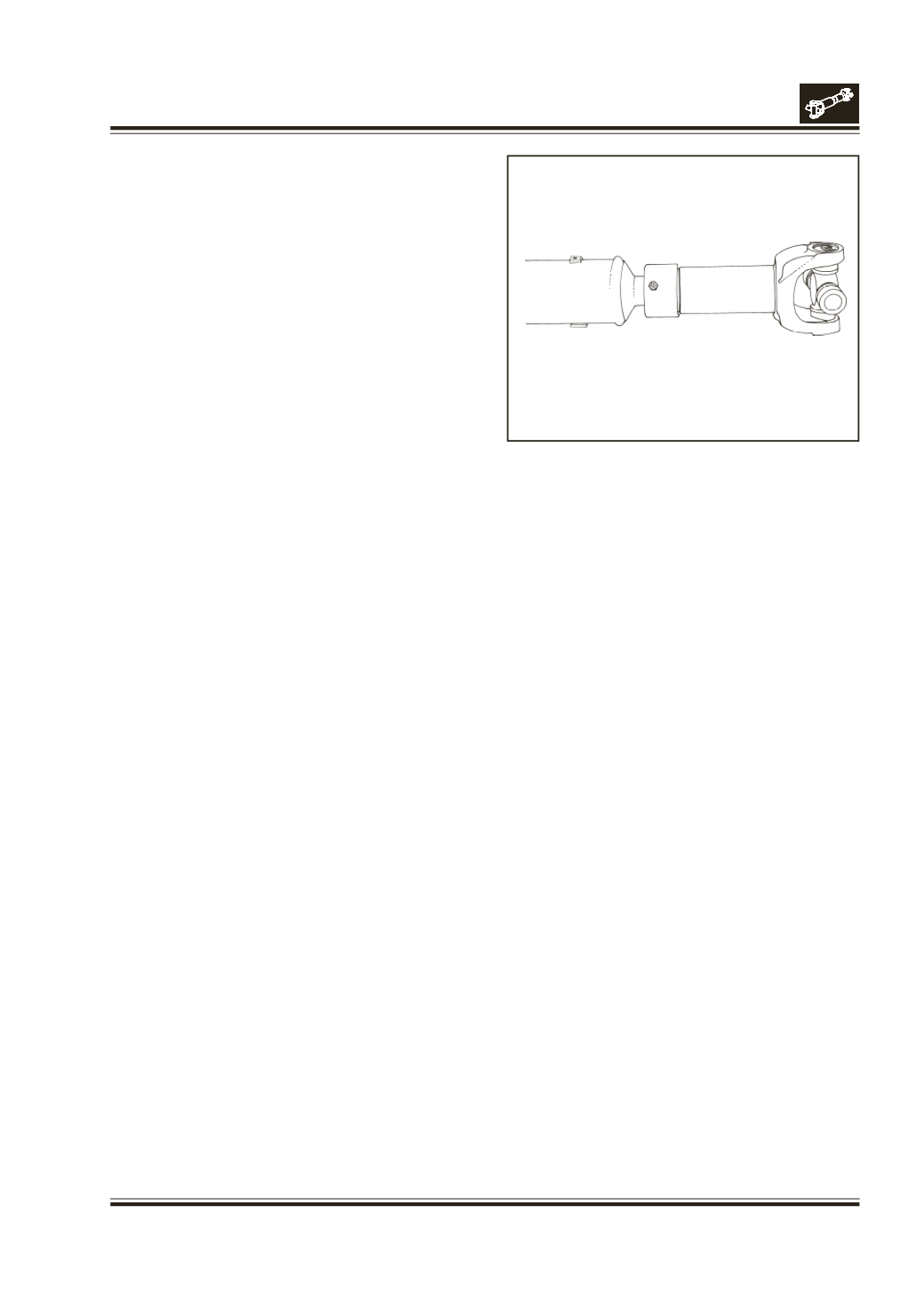
Fig. 28
Assemble tube shaft and slip yoke, making sure that
the alignment marks are in line. This will ensure that
slip yoke lugs and tube yoke lugs are in line. Fig.28
INSTALLATION :
PREPARING FOR INSTALLATION
In propeller shaft assembly, when there is replacement
of worn cross and bearing assemblies with a new kit,
it is desirable to rebalance it.
Take runout with entire drive shaft assembly mounted
on master tooling which locates on the outboard
bearing assemblies of the u-joint kit.
All yokes should be selected for dynamic balance to
eliminate as much unbalance as possible. During
balancing, the drive shaft again should be mounted
on the same master tooling or yokes.
After straightening, balance the entire assembly to the
specified limit.
INSTALLATION ON VEHICLE
Before installation ensure that :
Splines should slide freely with slight drag from spline
shaft seal.
Cross should flex and be free from excessive bind.
Note :
A slight drag is the most desirable condition
on a new cross and bearing kit. Excessive
looseness is not desirable and will result in an
unbalanced drive shaft.
Mounting Flange should be free from burrs, paint and
foreign substances which would not allow proper
seating at assembly.
While installing and servicing system balanced
assemblies, The following rules should be strictly
adhered to :
End yokes must not be rotated from their original
position during reassembly.
FOR INSTALLATION PROCEED INTHE REVERSE ORDER OF
REMOVAL.
Tighten the mounting nuts 8 bearing strap bolts to
specified torques.
Caution :
Self locking bolts used with bearingstraps
should not be reused.