


 1365 / 1526

PROPELLER SHAFT
12
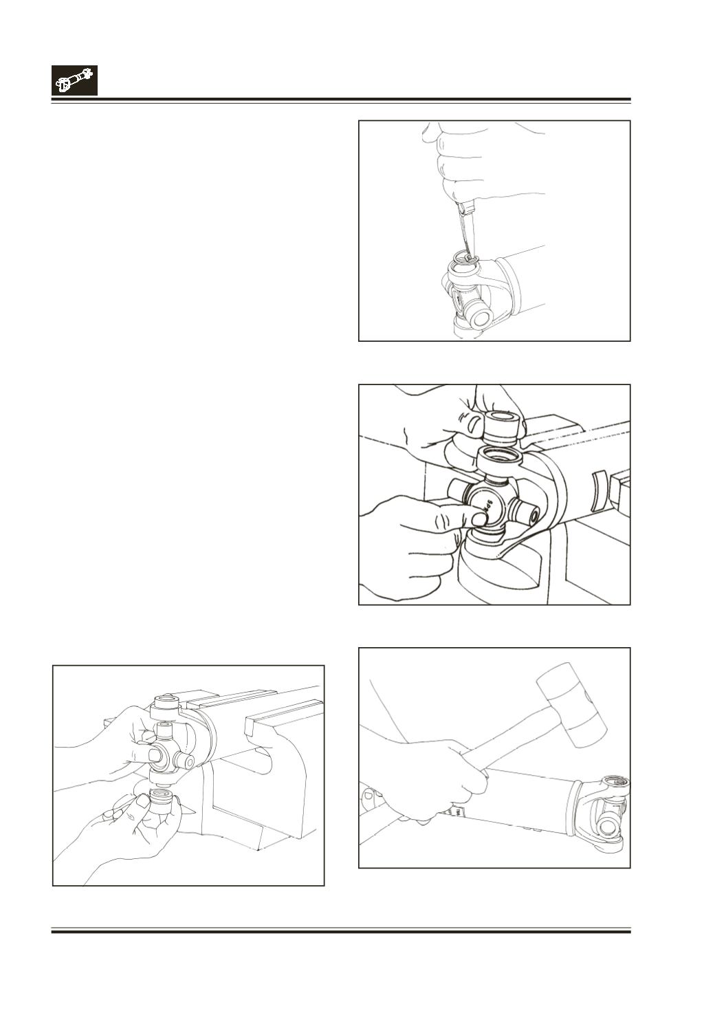
Fig. 25
Fig. 26
Fig. 27
Fig. 24
Move one end of the cross to cause a trunnion to
project through the cross hole beyond the outer
machined face of the yoke lug. Place a bearing
assembly over the trunnion diameter and align it to
the cross hole. Using an arbor press, hold the trunnion
in alignment with the cross hole and place a solid plug
on the upper bearing assembly.
Press the bearing assembly into the cross hole enough
to install a snap ring.
Fig.24
Install a snap ring.
Fig.25
Repeat the above two steps to install the opposite
bearing assembly.
Fig.26
If the joint is stiff, strike the yoke ears with a soft
hammer to seat the needle bearings.
Fig.27
Caution :
Be sure that snap rings are properly
seated in grooves.
Repeat the above steps at the opposite end of the
drive shaft in installing a second kit.
If removed earlier, the unitized seal should be
replaced with a new unit.
Install a new seal by generously lubricating the seal
lip and press it over slip yoke using a small arbor press.