


 995 / 1525

140
ENGINE2.2LDICOR
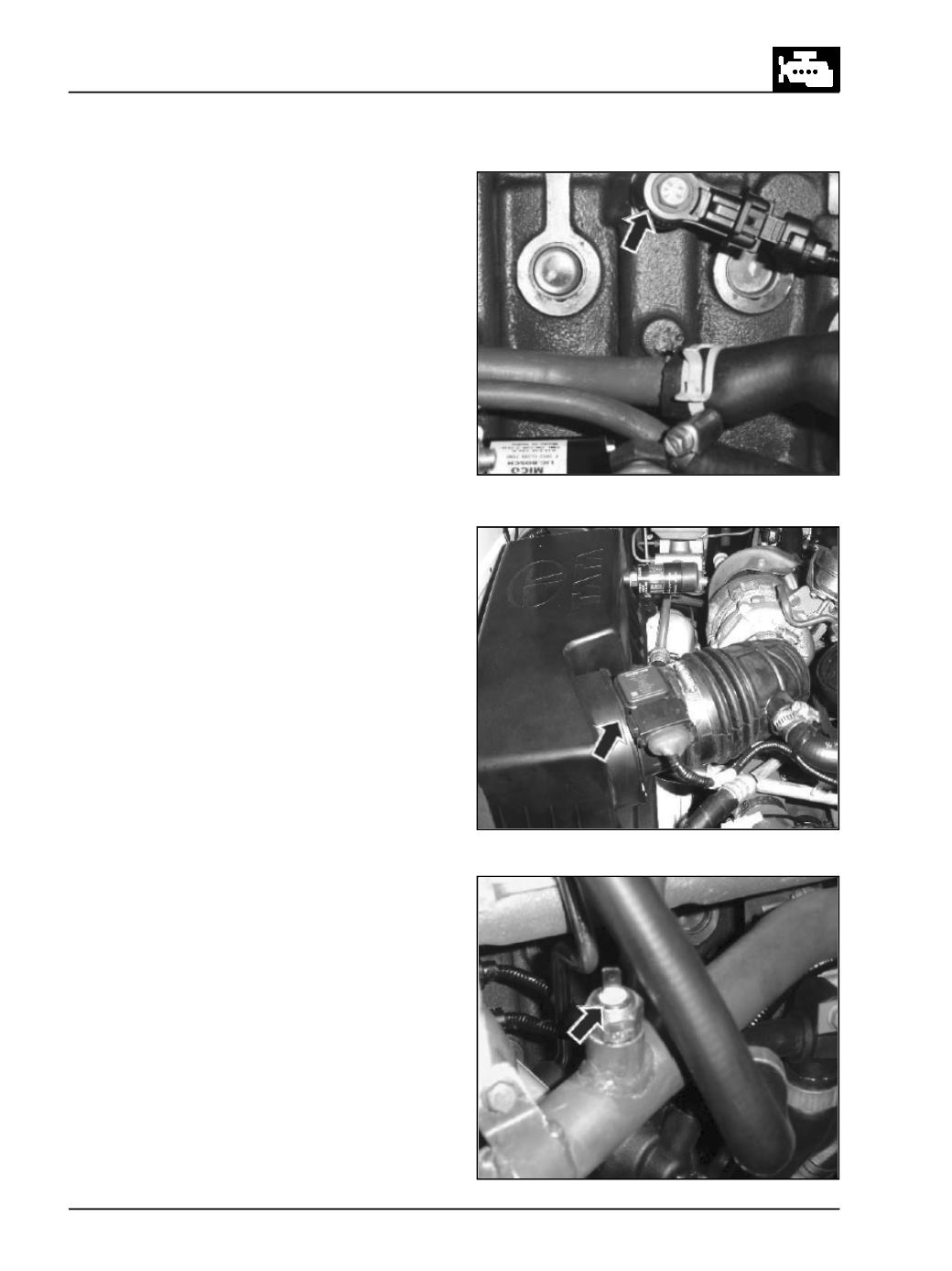
Fig. 227
Fig. 228
Fig. 229
4. Knock sensor (Accelerometer)
(Fig. 227)
The knock sensor is fitted on the cylinder block.
The knock sensor is a mechanical vibration
sensitive transducer mounted on engine block and
generates a voltage proportional to the
mechanical vibration in a pre determined location.
It senses the knocking in the cylinders during
combustion. It is a wide brand sensor gives high
output and flat response. The injector performance
is optimally controlled over the life of engine
based on knock sensor output.
Note
While assembling the knock sensor, ensure that it has
to be inclined 30 ± 5
0
as shown in the fig.
5. SIMAFSensor
(Fig. 228)
This sensor is mounted between air filter and
turbocharger. It gives Information about the
amount of air quantity & temperature entering the
engine.
This input is used by the ECU for corrections of
fuel quantity based on amount of air availability
for optimization of exhaust gas circulation & the
turbocharger control. While assembling, theAMF
sensor the point of the arrow should be towards
the Turbo charger.
6. Coolant Temperature Sensor
(Fig. 229 & 230)
A semi conductor material changes its resistance
when exposed to variable temperature source.
Resistance decreases as temperature increases.
There are two temp sensors fitted on water box.
White coloured sensor provides engine operating
temperature input to the Instrument cluster and
the brown coloured sensor provides engine
operating temperature input to the ECU.
Corrections for injection parameters are done by
the ECU based on coolant temperature to run the
engine with maximum efficiency at all
temperatures.