


 751 / 1525

44
BODY
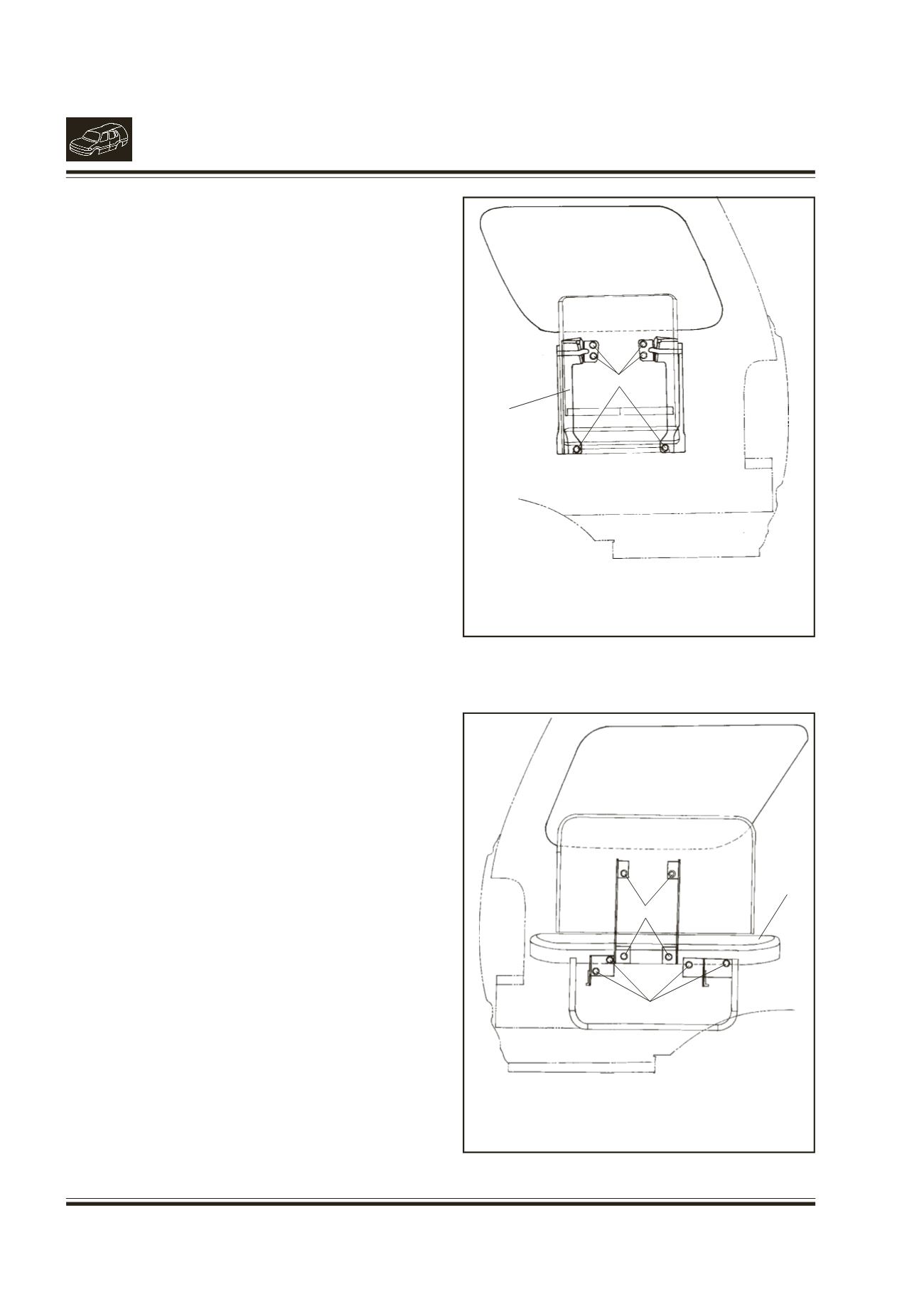
22. REMOVAL/INSTALLATION OF JUMP SEAT
(if fitted) (Fig. 26 & 27)
REMOVAL
l
Take down the jump seat RH by lifting up and
pulling out the back rest from top edge.
l
Remove the 6 mounting screws of jump seat RH
and remove the jump seat.
l
Pull out the back rest of jump seat LH and take
down the seat.
l
Remove 4 mounting screws of back rest and 4
mounting screws of jump seat LH. Remove the
back rest and jump seat LH.
INSTALLATION
l
Locate the jump seat RH with mounting holes on
inner side panel.
l
Fit the 6 hex screws (M8x20), spr. washers (B8),
bright washers (8.4) and tighten the screws.
l
Locate the back rest of jump seat LH with
mounting holes on inner side panel.
l
Fit the 4 hex screws (M8x20), spr. washers (B8),
bright washers (8.4) and tighten the screws.
l
Locate the jump seat LH with mounting holes on
inner side pannel.
l
Fit the 4 hex screws (M8x20), spr. washers (B8),
bright washers (8.4) and tighten the screws.
19. BODY MOUNTING LOCATIONS
(Fig. 28)
Body is mounted on the chassis frame as shown
in fig.
Fig. 26.
1.
MOUNTINGSCREWS
2.
JUMP SEAT RH
1
Fig. 27.
1.
MOUNTING SCREWS OF BACK REST
2.
MOUNTING SCREWS OF JUMP SEAT
3.
JUMP SEAT LH
1
2
2
3