


 697 / 1525

47
ELECTRICALS
17G. GLOW PLUG TIMER :
Function
It provides electrical supply to glow plugs for
controlled period according to ambient temperature.
Location
It is located on the firewall inside the engine
compartment.
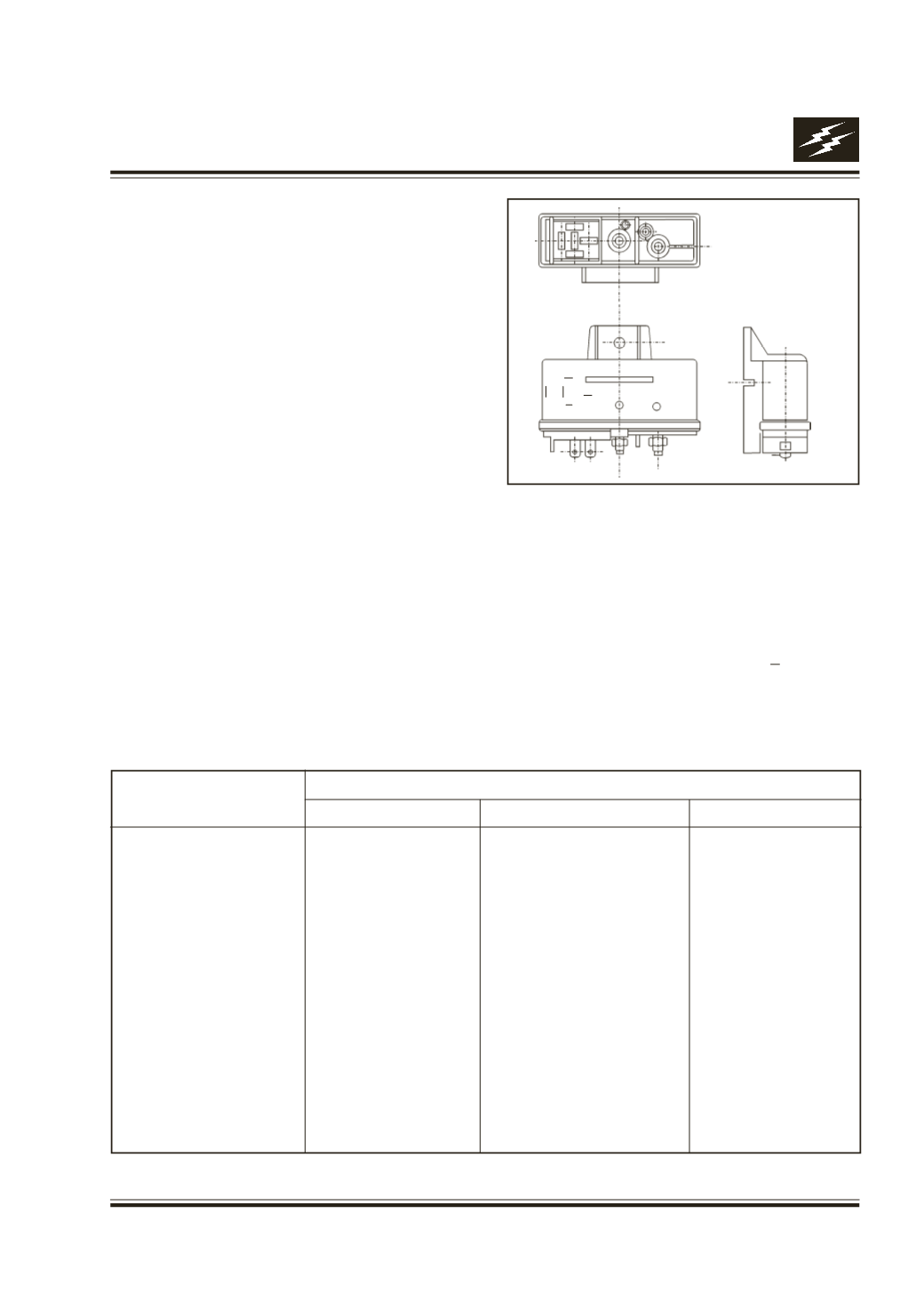
Connection details Fig. 51
Operating sequence
a.
‘IG’ contact ‘ON’- indicator lamp burns upto
duration as decided by zone control, lamp
extinguishes as shown in table 1. Glow plug
continues to remain ‘ON’ even after lamp has
extinguished, engine should be started by
making ‘ST’ contact ‘ON’. If engine is hot, ‘ST’
contact may be made ‘ON’ without waiting for
indicator lamp to extinguish. However, if ‘ST’
contact is not made ‘ON’, the glow plug supply
is switched after a period as shown in the table
1. This is a safety feature.
b.
‘ST’ contact ‘ON’ - with ‘IG ON’, glow plugs
continue to remain ‘ON’ while engine is cranked.
Fig. 51
GLOW PLUG TIMER
1 5
3
4
2
7
6
(
0
C) TEMP
Performance Check :
1.
Lamp on time
As per table
2.
Safety shut Off time
As per table
3.
Post glow time
As per table
4.
Over voltage protection 14.5 + 0.5
5.
Lamp output and glow plug output are
short circuit protected.
Table 1 :
-30
30
40
200
-20
23
33
200
-10
17
27
200
0
10
20
200
10
8
18
200
20
6
16
200
30
4
14
120
40
4
14
90
50
4
14
60
60
4
14
30
70
4
14
15
80
4
14
0
TIME IN SECONDS
PRE GLOW
SAFETY SHUT OFF
POST GLOW