


 670 / 1525

20
ELECTRICALS
9. FUEL GAUGE TANK UNIT
Removal :
l
Remove Fuel Tank assembly. Fig. 12
l
Release clip & disconnect fuel feed hose.
l
Release clip & disconnect fuel return hose.
l
Remove electrical connections.
l
Remove 6 nuts securing Float Unit from the fuel
tank.
l
Remove seal from the Float Unit.
Fitment :
Please follow reverse procedure
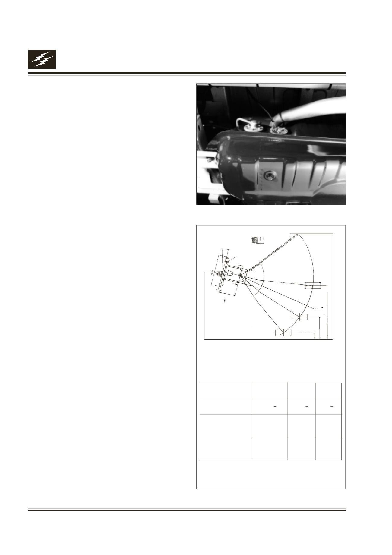
Testing / Checking : Fig. 13
The sender is a float operated rotary potentiometer
which provides a variable resistance to ground for
the output from the gauge. When the sender float is
at its lowest point, indicating an empty fuel tank, the
resistance to earth is at its lowest. The resistance is
sensed by the gauge which positions the needle
accordingly.
Use ohm-meter to confirm that the resistance of the
fuel level sensor (Fuel Tank Unit) changes with the
level of float position.
Temp. Gauge : Refer Fig. 9
When the engine reaches normal operating
temperature, the gauge will rest at the mid-point of
the temperature scale. If the engine coolant
temperature becomes too high, the pointer will rise
to the red segment of the scale to warn of an engine
cooling fault. At this position the engine coolant
temperature is too high and continued operation could
result in engine damage; the vehicle should be
stopped as soon as possible.
Fig. 12
Fig. 13
Calibration Details :
Float Position Empty Half
Full
Float Height
16.5
+2
133
+2
262
+2
Resistance
10
104 186
1N OHMS
Tolerance
+0
+8
+8
in OHMS
-4
15.00
DETAIL ‘A’
SCALE N
S
B
75.00
M4.00
X0.7
B
T
(90.00)
37.50
4.00
169.00
Fuel Tank Unit
R176.00+2
HALF
EMPTY
RESERVE
FULL