


 633 / 1525

13
POWER STEERING
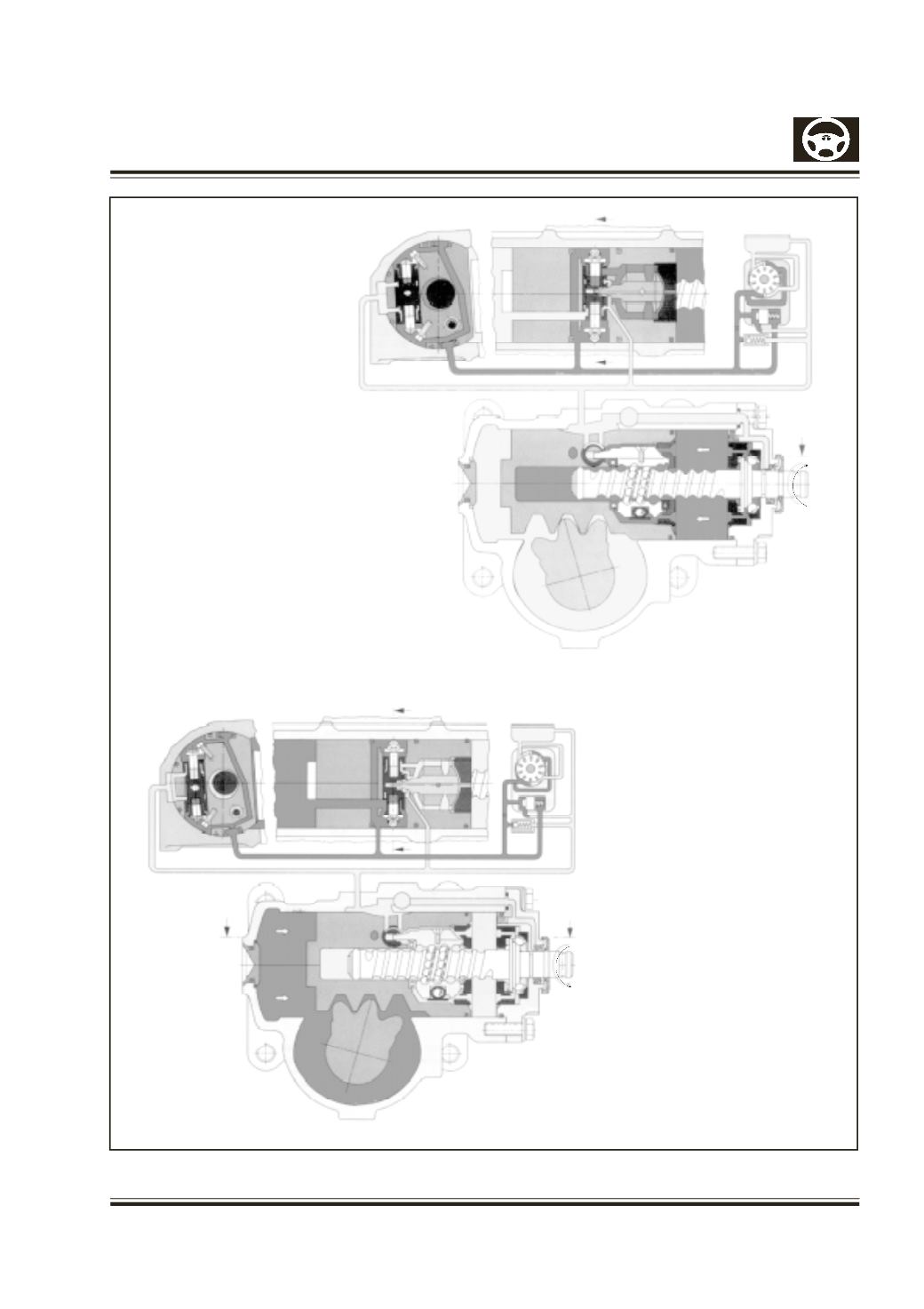
Fig. 2 & 3
Fig.2 VALVE IN OPERATING
POSITION, steering wheel
turned clockwise, valve spool
moved to the right, pressure oil
gets into the cylinder chamber,
left cylinder chamber connected
to return flow.
Fig.3 VALVE IN OPERATING
POSITION, steering wheel
turned anti-clockwise, valve
spool moved to the left,
pressure oil gets into the
cylinder chamber only, right
cylinder chamber connected to
return flow.