


 60 / 1525

31
4 DLT ENGINE
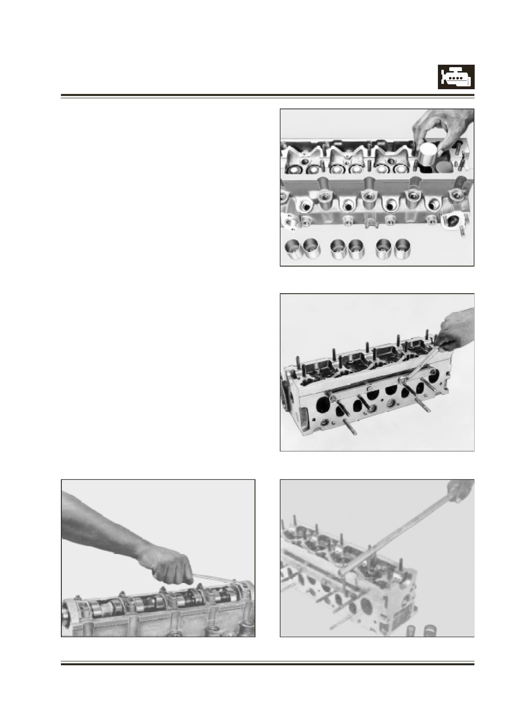
Fig. 58
Fig. 59
Fig. 60
Fig. 57
U
nscrew cam shaft bearing cap mounting nuts (first
5th and 1st caps, next 4th and 2nd caps, lastly 3rd
cap.) Refer figure 57.
R
emove cam shaft bearing caps.
R
emove cam shaft with oil seal.
R
emove tappets and shims and place them carefully
in correct sequence. Refer figure 58.
F
it support rail, 2654 5890 05 06 to cylinder head.
Refer figure 59.
W
ith spring compressor, 2654 5890 05 07 compress
valve springs and remove valve lock halves. Refer
figure 60.
R
emove valve lock retainers, valve springs, valve
spring seats and valves. Place them in correct
sequence.