


 459 / 1525

34
REAR AXLE
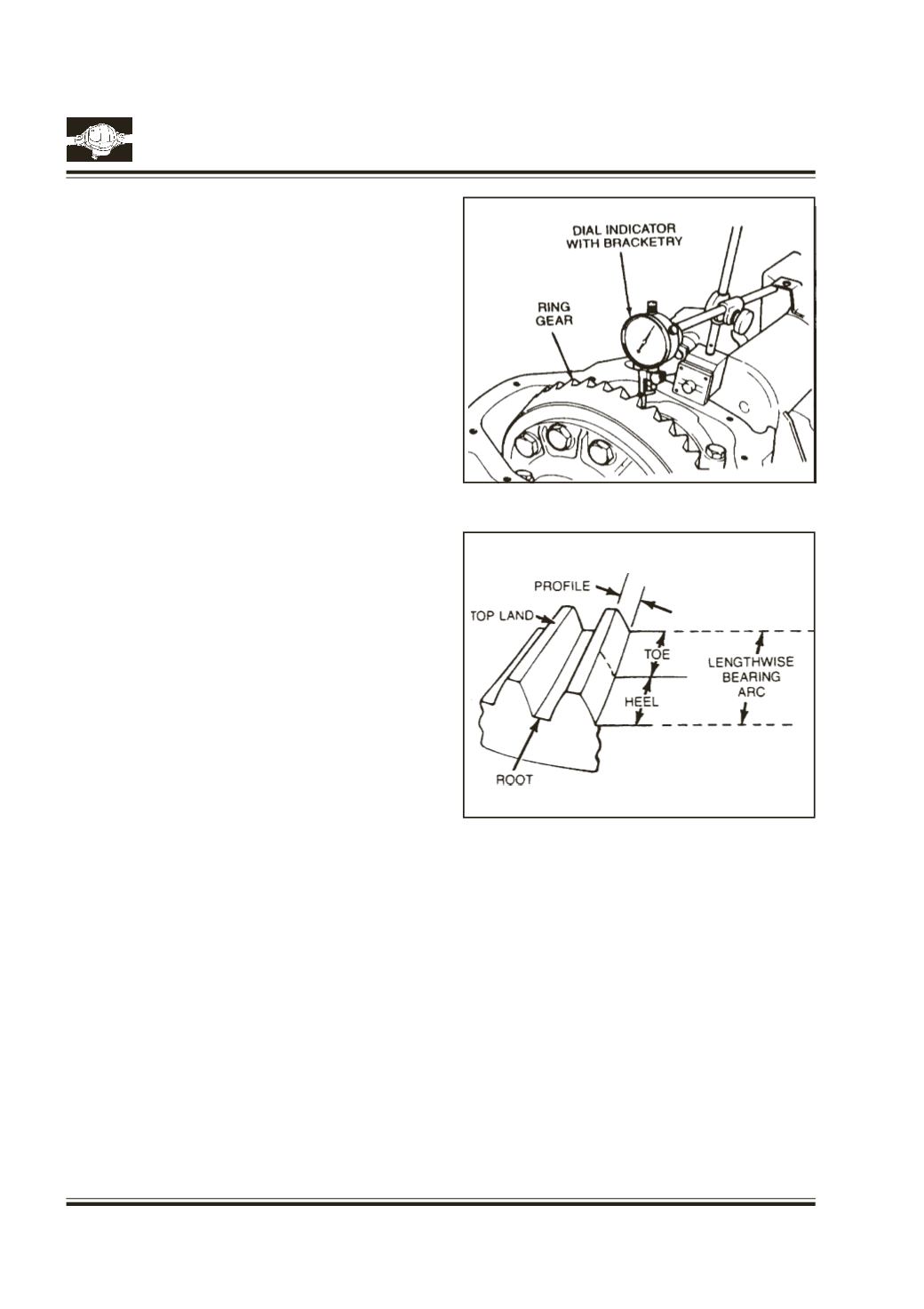
Fig. 70
Fig. 69
Check ring gear and pinion backlash at three equally
spaced points with dial indicator.
Fig. 69
Backlash tolerance is 0.13 to 0.20 mm. and should
not vary more than 0.08 mm. between the three
points checked.
High backlash is corrected by moving the ring gear
closer to the pinion. Low backlash is corrected by
moving the ring gear away from the pinion.
These corrections are made by switching shims
from one side of the differential case to the other.
If backlash is to specification CHECK the ring gear
and pinion tooth contact pattern.
INTERPRETING RING GEAR AND PINIONTOOTH
PATTERN
The toe of the gear tooth is the portion of the tooth
surface at the end toward the center. The heel of the
gear tooth is the portion of the tooth surface at the
outer end. The top land of a gear foot is the surface
of the top of the tooth.
Fig. 70
The illustrations explain how contact pattern shift
as gear location changes.
When making pinion position changes, shims should
be changed in steps of 0.05 mm minimum, until cor-
rect pattern has been obtained.
When a change in backlash is required backlash
shims should be changed in the range of 1.5 times
the amount of backlash required to bring the gears
into specification. For example, if the backlash must
be changed by .10 mm the shim pack should be
ranged by .15 rnm as a starting point. The actual
amount of backlash change obtained will vary, de-
pending upon the ratio and gear size.
Note:
Making changes involves two variables. Ex-
ample: if you have the backlash set correctly
to specifications and you change the pinion
position shim, you may have to readjust the
backlash to the correct specification before
checking the pattern. Refer to pattern inter-
pretation.