


 144 / 1525

105
4 DLT ENGINE
Installation of accelerator cable
1.
Insert accelerator cable pedal end inside the
firewall hole.
2.
Insert inner cable end in accelerator pedal.
Refer fig. 194 & 195 RHD/LHD pedal end.
3.
Locate accelerator cable in clamp on firewall as
shown in the Fig. 194 & 195 and route the cable.
4.
Loosen the nut from the threaded end of the cable.
Engage the threaded end of the cable in throttle
body bracket. Insert inner cable end socket in
the FIP lever ball pin Fig. 196. Lock the socket
with spring pin No. 14, lock the ball pin No. 11
with lock plate No. 12.
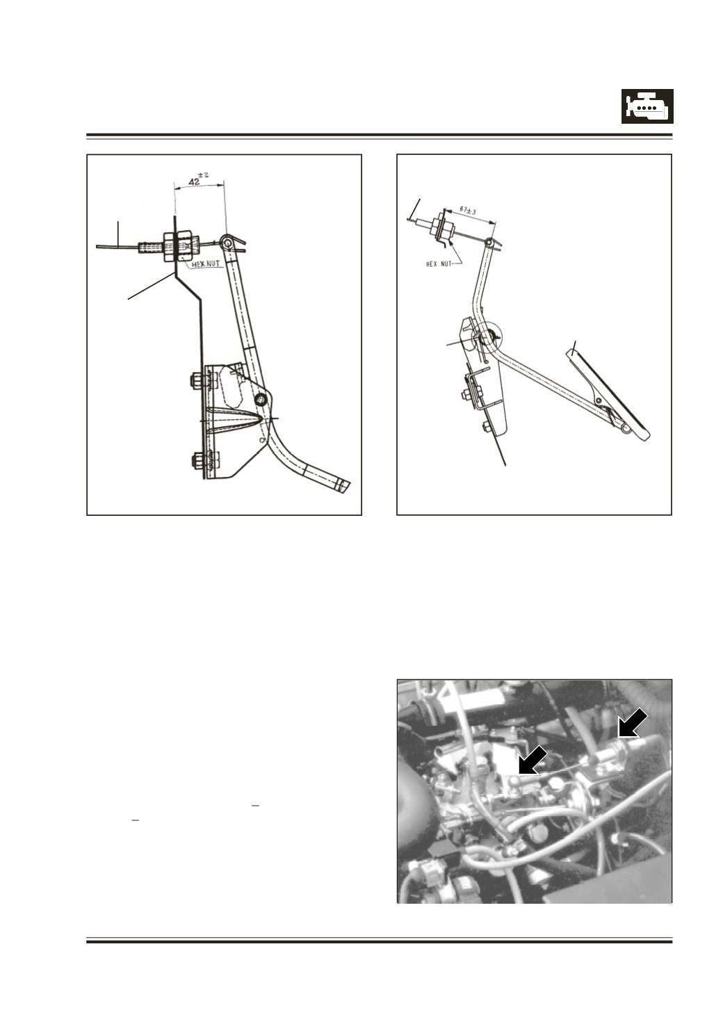
5.
Adjust the dimensions 67 + 3 mm for RHD and
42 + 2 mm for LHD. Ensure tightness in inner
cable by adjusting the nuts on threaded end of
the cable.
6.
Ensure that when accelerator pedal is fully
depressed, full travel of throttle lever is achieved.
Removal of Accelerator cable
Removal of accelerator cable is in reverse order of
installation.
Fig. 194
Fig. 195
mm
mm
Fig. 196
LHD
RHD
Inner Cable
Fire wall
Accelerator pedal
Inner Cable