


 1266 / 1525

ENGINE
99
Fig. 10
Fig. 9
8 Select thrust washers of correct size to maintain
permissible crankshaft axial play.
9 Re-chamfer oil holes onmain journals and crankpins
to avoid scoring of newbearing shells.
10 Finish journals andpins by lapping themwith320grit
lappingclothof suitablewidth.Mount counterweights
and tighten mounting bolts to specified torque.
Ensure that counterweights are assembled in their
original respective positions.
11 Checkdimensionsofmain journals, crankpinsandalso
runout ofmain journals.
12 Thoroughlycleanoil holes incrankshaftwithkerosene
jet andwire brush.
13 Recheck for cracks andbalance crankshaft after every
re-grinding.
14 Apply grease to all machined surfaces if crankshaft is
to be stored. Crankshaft must always be stored in
vertical position.
15 Fitmainbearing shellsmaking sure that locating lugs
are properly seated in notches of parent bore of
crankcase andmain bearing cap.
16 Mountmainbearing capswith shells on crankcase in
position and tighten mounting bolts to specified
torque.
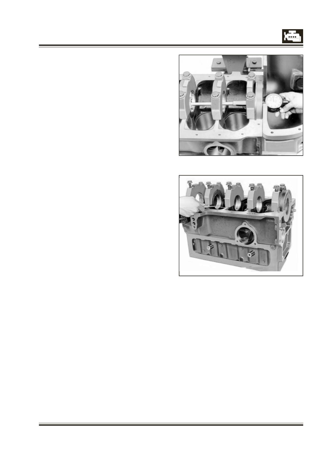
17 Measure main bearing bores using internal
measuring instrument. Fig. 9.
NOTE
If parent bore diameter is maintained within
specification, proper bearing dimension is
automatically achieved. However, it must be
ensured by physically checking bearing size.
18 Loosen main bearing cap bolt on tappet side and
check bearing pretension with feeler gauge.
Fig. 10.
19 Remove main bearing caps again.
NOTE :
Main bearing shells, no matter which repair stage
are precision finished and must on no account be
bored or scraped.