


 919 / 1588

32
ENGINE2.2LDICOR
l
Install matching size valve guide in cylinder head
using drift (Part No.2868 5890 06 05) and spacer
(Part No. 2653 5890 06 01). (Fig. 64)
l
Fit Valve guide oil seals
Fig. 64
Valve Seat
l
Check valve seat height with respect to cylinder
head mating surface. Replace valve seat inserts if
they are worn out beyond specified limit.
l
Cut exhaust and inlet valve seats with a general
45 deg. cutter. (Fig. 65)
Fig. 65
NOTE
VALVESEATMUSTBEABSOLUTELYFAULTLESSAND
WITHOUTANYCHATTERMARKS
l
If necessary lap the valve seats to a smooth and
even finish by using suitable hand pump grinder
or a lapping paste and valve itself.
l
Smear valve seat with carbon blue. Install valve in
guide and turn it slowly under axial pressure.
l
CONTACTLINEONVALVESEATMUSTBEAROUND
ENTIRECIRCUMFERENCEATEQUALWIDTH
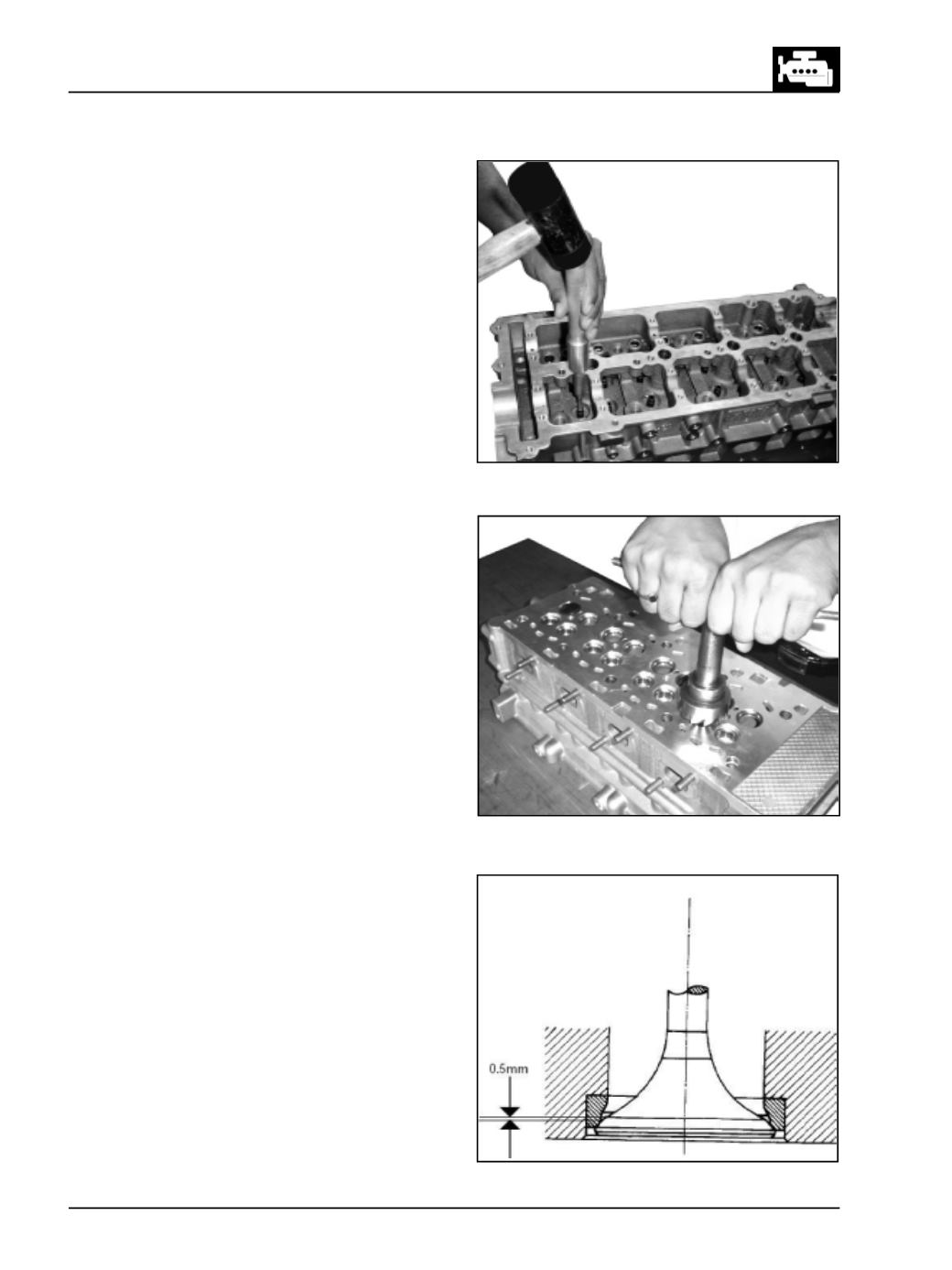
l
Distance between narrow diameter of valve face
to contact line should be minimum 0.5 mm.
(Fig.66)
l
Check for leakages through valve seat by pouring
gasoline on valve head. Gasoline must not seep
past valve seat.
Fig. 66