


 853 / 1588

41
AIRCONDITIONING
C. TROUBLESHOOTINGON COOLER ELECTRICAL CIRCUIT
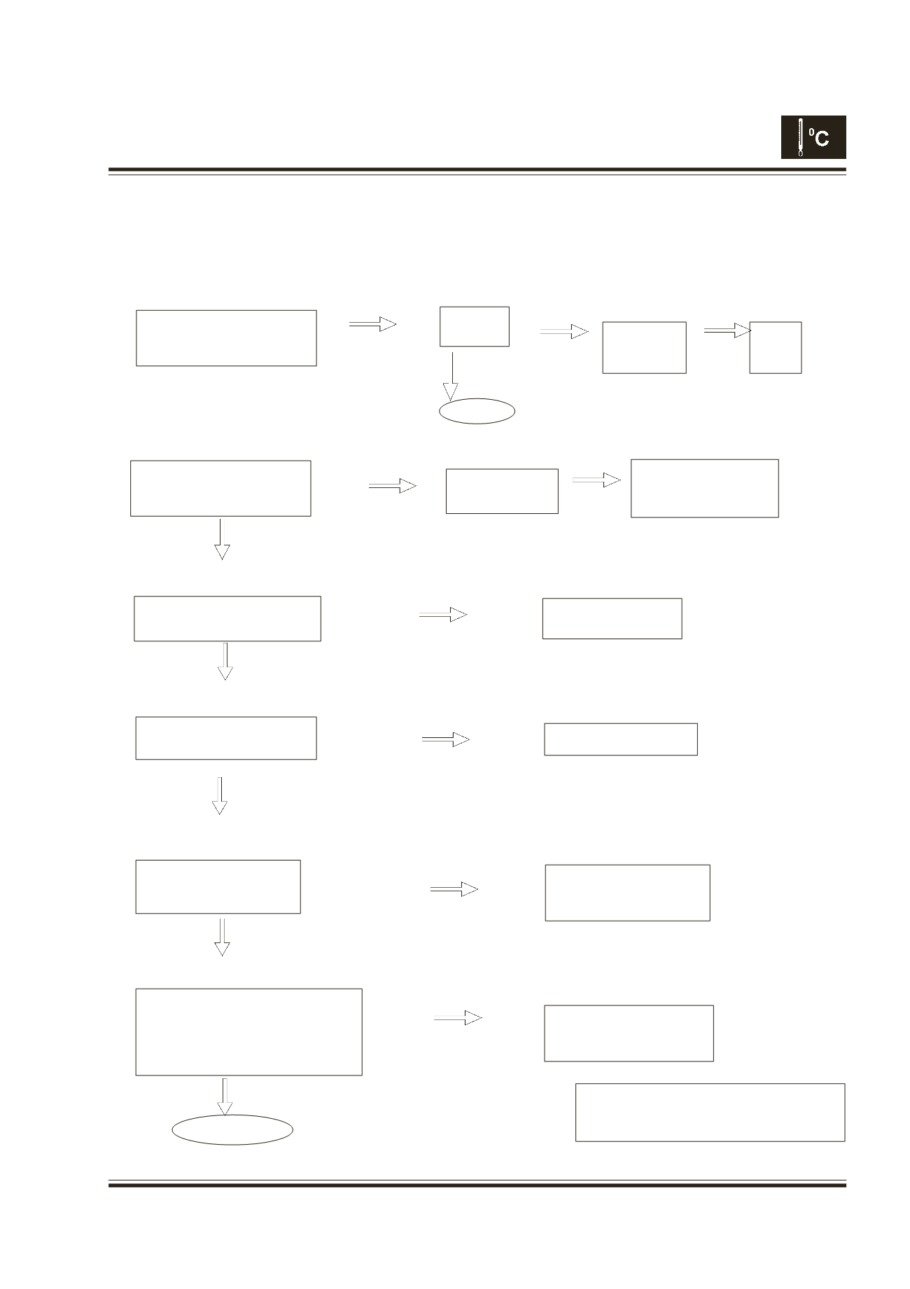
1. Troubleshooting Flow Chart
After making sure that the blower circuit operation is good, troubleshoot the cooler circuit in the following
procedures.
STEP 1 CHECK A/C SWITCH FUNCTION
STEP 2 CHECK MAGNETIC CLUTCH
STEP 3 CHECK POWER SOURCE TO CLUTCH
STEP 4 CHECK MAGNETIC CLUTCH RELAY
STEP 5 CHECK OUTPUT FROM AMPLIFIER
STEP 6 CHECK INPUT TO AMPLIFIER
With blower operated, push on
A/C switch, and check whether
A/C switch lamp is lit.
No
With A/C switch and blower
switches On, check whether
magnetic clutch is On.
Yes
Check voltage of 1-pole connec-
tor for the magnetic clutch.
Check voltages to clutch relay
Connector
No Battery Voltage
or No Grounding
Check output voltage from
amplifier.
Terminal 1A – OK
No Good
Inspect
A/C fuse
OK
Blown or
Bad Contact
Check wiring between
A/C fuse and the blower
circuit.
Check magnetic clutch
coil.
Step 4-1
Check relay and its wiring
Check continuity of wiring
between amplifier and mag-
netic clutch relay.
Check input
voltage to
A/C fuse
12V
Replace it
Check
A/C
switch
Check condenser
Fan relay circuit
12V
OK
OK
OK
Check each input voltage and sig-
nal from sensor such as Ther-
mistor, Dual Pressure S/W Engine RPM
signal from eng. ECU. Also
check the earth circuit for amplifier.
OK
Replace amplifier
Check sensor and its wiring,
which don't input correct sig-
nal.
Important
Also A/C idle up check should be done Visu-
allsy regardless of above troubleshooting result,
No
No Good
OK