


 544 / 1588

ABS
16
ANTI-LOCK BRAKES
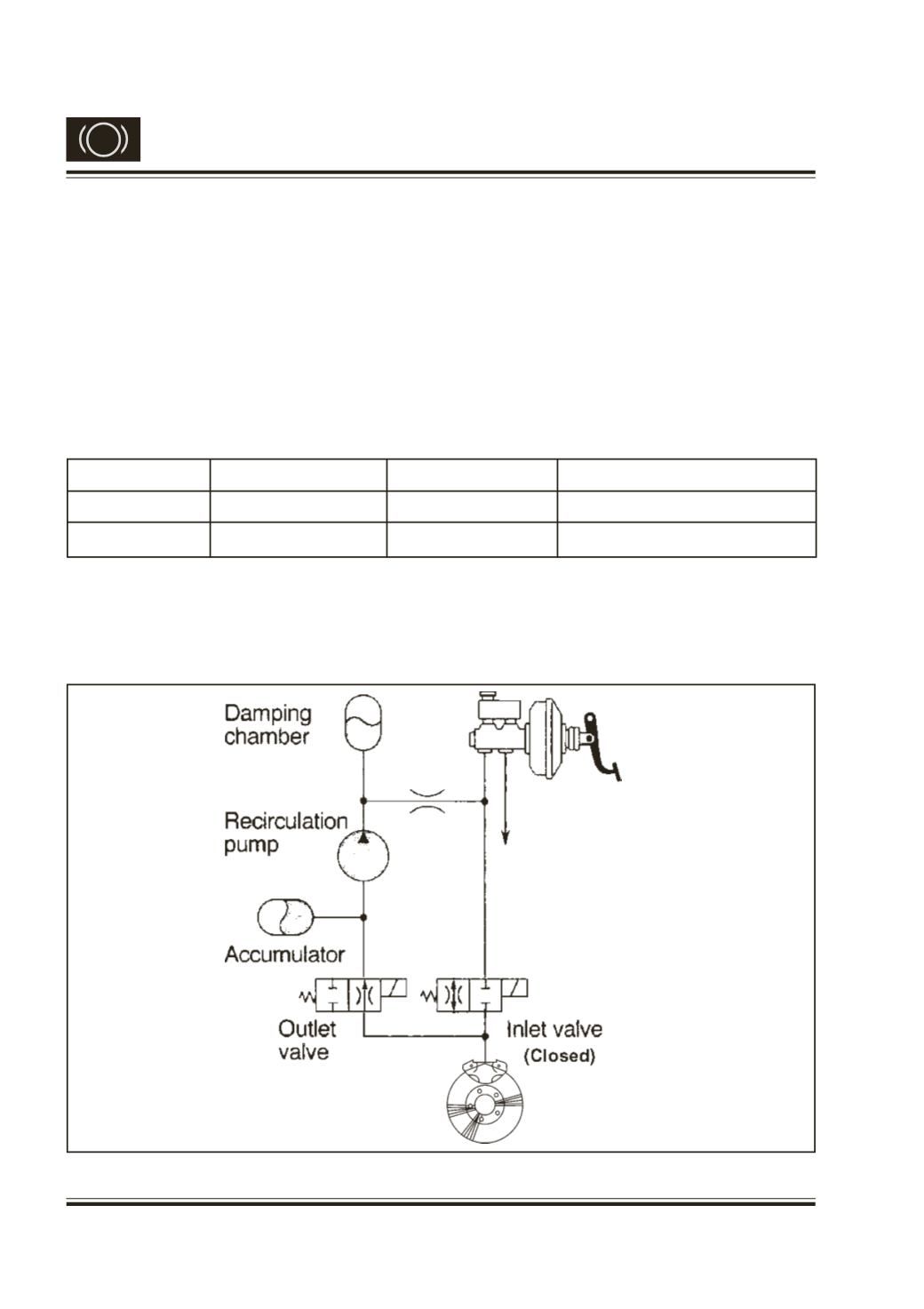
B. Pressure Reduction Phase
Even after the pressure hold phase, if already the
existing pressure in the wheel cylinder is too much,
by which the wheel is further tending to lock, then
the ECU activates outlet solenoid valve and lets
some amount of brake fluid to reach the accumulator,
which serves the purpose of temporary storage.
ECU activates both Inlet & Outlet solenoid valves.
The closed Inlet solenoid valve shuts the liquid
channel from master cylinder. The outlet valve opens
and connects the wheel circuit to the reservoir. Refer
Fig. 7. Brake fluid gets discharged into the
accumulator. The recirculation pump (which is driven
by a motor which is not shown in the figure) pumps
the brake fluid back to the master cylinder through
the damping chamber. The damping chamber avoids
the pulsations of the returning brake fluid from
getting transferred to the driver’s foot. The pressure
reduction is continued till the wheel speed recovers
to the vehicle reference speed.
Solenoid valve
Electricity status
Valve open-close
Open-close channel
INLET
ON
CLOSE
Master cylinder-Wheel cylinder
OUTLET
ON
OPEN
Wheel cylinder-reservoir
Fig. 7
(Open)