


 353 / 1588

21
SUSPENSION
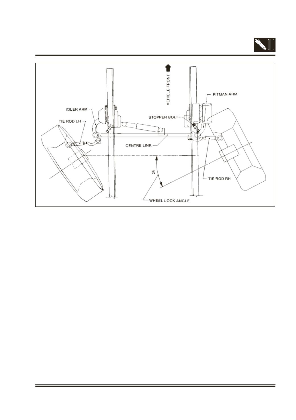
7D. WHEEL LOCK ANGLE ADJUSTMENT (Fig.24)
Wheel lock angle is to be set with the help of
stopper bolts fitted in the bracket on chassis
frame. Proper adjustment of wheel lock angle
ensures correct turning circle and also safeguards
the steering linkages.
l
Place turn tables beneath front wheels, ensure
that wheels are centrally positioned on the turn
table.
l
Make the front wheels in straight ahead position
and set turn table scale to ZERO.
l
Press brake pedal and turn steering to right till a
reading of 26 to 25
0
is attained on the left hand
wheel turn table. In this condition adjust stopper
bolt on LH side of chassis bracket to touch the
idler arm and lock adjusting bolt with lock nut.
l
Similarly turn steering to left till a reading of 26 to
25
0
is attained on right wheel turn table. In this
condition adjust stopper bolt on RH side chassis
Fig. 24 – Wheel lock angle adjustment
bracket to touch the pitman arm. Lock stopper
bolt with lock nut.