


 318 / 1588

16
TRANSFER CASE
Self Diagnosis of ECU :
Refer fig. 4&5
ECU detects transfer case system malfunctions and
indicates malfunctioning part (s) through flashing
indictor light mounted on dashboard. The operator
will be alerted of fault condition by continuous
illumination of both 4WD HI and 4WD LO lights, on
dash board when ignition is on.
A Service connector is provided to indicate the fault
codes in binary.Connect one end of service connector
in to the pin hole No. 22 in ECU connector and other
end to the ignition switch. (In case a connector is
provided to hole No. 22. Connect the end to it.) The
flashing (ON/OFF) of indicator light will show Binary
code (as illustrated in the table). Identify the
malfunctioning part and replace it.
L1 L2 L3 Binary Decimal Fault with
Code
Equivalent
Off Off On 001
1
ECUModule
Off On Off
010
2
Shift Motor
Off On On 011
3
Synchro-
nizer Clutch
On Off Off
100
4
Speed
Sensor
On On Off
110
6
Selector
switch
On On On 111
7
Motor
Position
switch
DiagnosticTable
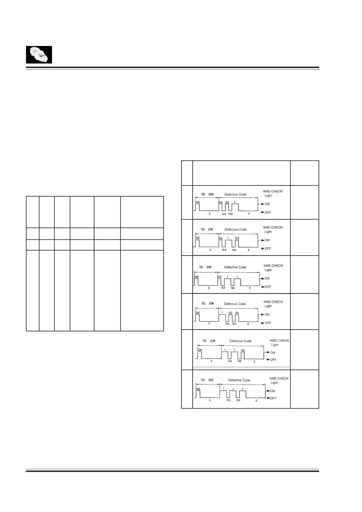
Connect a service connector.
Turn the ignition switch on. 4WD CHECK indicator will
turn on for a fraction of second and turn off for 3
seconds.
Then it will display a defective code 3 times
continuously.
NO.
Defect Codes
Malfunc-
tioning
Part
1
ECU
2
Shift
Motor
3
Synchro
nizer
Clutch
4
Speed
Sensor
6
Selector
Switch
7
Motor
Position
Sensor
Fig. 4
Fig. 5
If only one part is malfunctioning, the indicator light
will display defective code three times continuously.
If more than two parts are malfunctioning, the first
malfunctioning part will be displayed three times and
then the other malfunctioning parts will be displayed.
After repair, clear the fault stored in thememory.Ground
the service connector and keep ignition 'on' for five
seconds to erase defective code.
Note :
Before replacing the malfunctioning parts
with defective code. Check the wires and
connectors for proper condition.
Use only 12V 3Watt bulb for diagnostic
purpose.