


 1323 / 1588

ENGINE
124
Fig. 4
Fig. 2
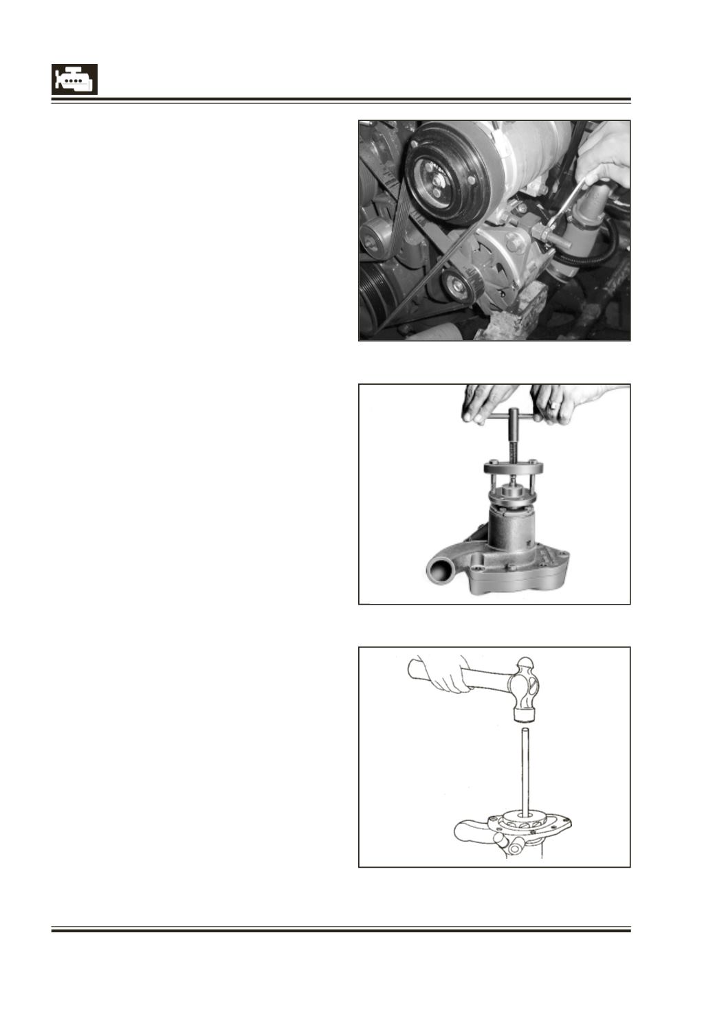
Fig. 3
REMOVAL OF WATER PUMP
1 Drain cooling water mixed with anti-corrosive/
anti-freeze agent into clean container so that it
can be reused.
2 Remove by-pass hose with thermostat.
3 Slacken and remove poly ‘V’ belt. Fig. 2.
4 Unlock and unscrew mounting bolts for pulley and
remove water pump pulley.
5 Remove cooling water inlet hose from water
pump.
6 Unscrew four water pump mounting bolts from
cylinder block and remove water pump.
DISASSEMBLY OF WATER PUMP
1 Remove split pin and loosen the castle nut holding
pulley hub on water pump shaft.
2 Remove pulley hub from water pump shaft using
puller 2576 5890 35 22. Fig. 3.
3 Unscrew and remove water pump rear cover
mounting bolts. Remove rear cover.
4 Unlock and remove four screws and plate holding
water pump bearing outer race. Remove plate
with grease seal, shims and gasket and also outer
bearing outer race.
5 Place water pump on housing of support, 312 589
05 33 and press out water pump shaft with
bearing assembly from impeller. Fig. 4. Use a steel
bar 200 mm long and 15 mm dia meter for
pressing out shaft. Remove inner grease seal from
housing.
6 Place water pump shaft on a tube supporting
inner bearing inner-race with shaft taper end
facing upwards. Fix nut on threaded end to
protect it from damage and press out shaft from
bearings and spacer tube. Remove slinger from
shaft.
7 Knock out outer race of inner bearing from pump
housing with drift, 321 589 01 35.